

![]()
- Customer: University of Massachusetts Lowell (UMass Lowell)
- Country: U. S. A.
- Industry: Educational / Academy
- Solution: Moldex3D Studio, Expert, Flow, Pack, Cool, Warp, Fiber, FEA Interface
The Plastics Engineering (ESE) program is administered by the Department of Plastics Engineering, UMass, Lowell. Various levels of external support allowed the program to continue its mission of being recognized for excellence in plastics engineering education and research. (Source)
Summary
Rear derailleurs are the structural components for bike gears (Fig. 1). They are commonly made using either aluminum, steel, or fiber-reinforced thermosets composites. The component is usually an assembly of two metal parts that hold the chain in between. This project proposed to use process and structural simulation to re-design the component for manufacturing with a fiber-reinforced resin. This approach includes re-design and optimization of the part for injection molding, and structural analysis using the CAE results as inputs for the orthotropic material properties. Coupling the process simulation with the structural FEA allow for advanced optimization of part and mold design.
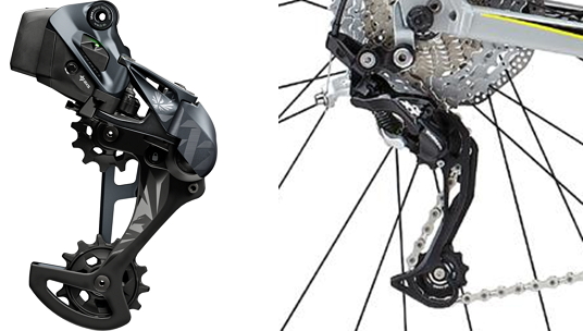
Fig. 1 Bike rear gear assembly examples
Challenges
- To optimize the part and mold design for a fiber-reinforced structural component
- To minimize the part deflection caused by fiber orientation
- Control of process parameters for warpage optimization and minimum deflection (Fig. 2)
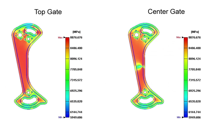
Fig 2. Warpage results of the original design: elastic modulus
Solutions
The UMass Lowell team used Moldex3D to study the correlation between part design, mold design, fiber orientation, and structural properties. The software was used to validate fiber content and resin selection from a processing and functional perspective. The approach demonstrates the effectiveness of combining process simulation and structural simulation for redesigning products with plastic reinforced polymers.
Benefits
- Effective part redesign with plastic and validation of structural properties against original design (metal)
- Accurately predicted the mechanical performance of the designed part using FEA interface the process-related material properties.
- Optimized fiber content and orientation through optimal mold design
- Avoided costly mold prototyping and reconstructions through coupling of processing and structural simulation.
Case Study
The objectives of this study were to design a structural component using fiber-reinforced thermoplastic to replace metal. The UMass team used Moldex3D to analyze the effects of processing on orthotropic material properties, and tried to optimize the design for manufacturing, considering fiber content, part design and mold design. Then, they validated product design by coupling Moldex3D and FEA software.
To achieve desired structural properties, the team proposed several designs with (1) different gate locations, (2) fiber content and (3) the process parameters (Fig. 3). Three different gate locations and other designs were analyzed; the optimum design was defined considering the fiber orientation and the structural properties.
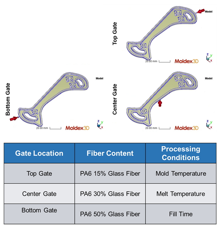
Fig 3. Gate locations and analysis approach
The UMass Lowell team tried to optimize the fiber orientation and the elastic modulus using Moldex3D, the results are shown below. (Fig. 4 & 5).
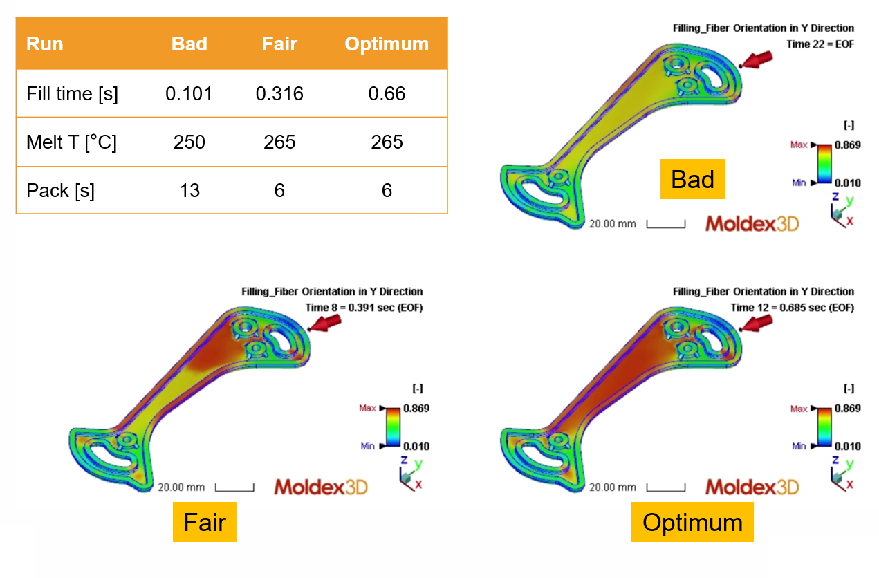
Fig 4. Optimizing fiber orientation by adjusting process parameters
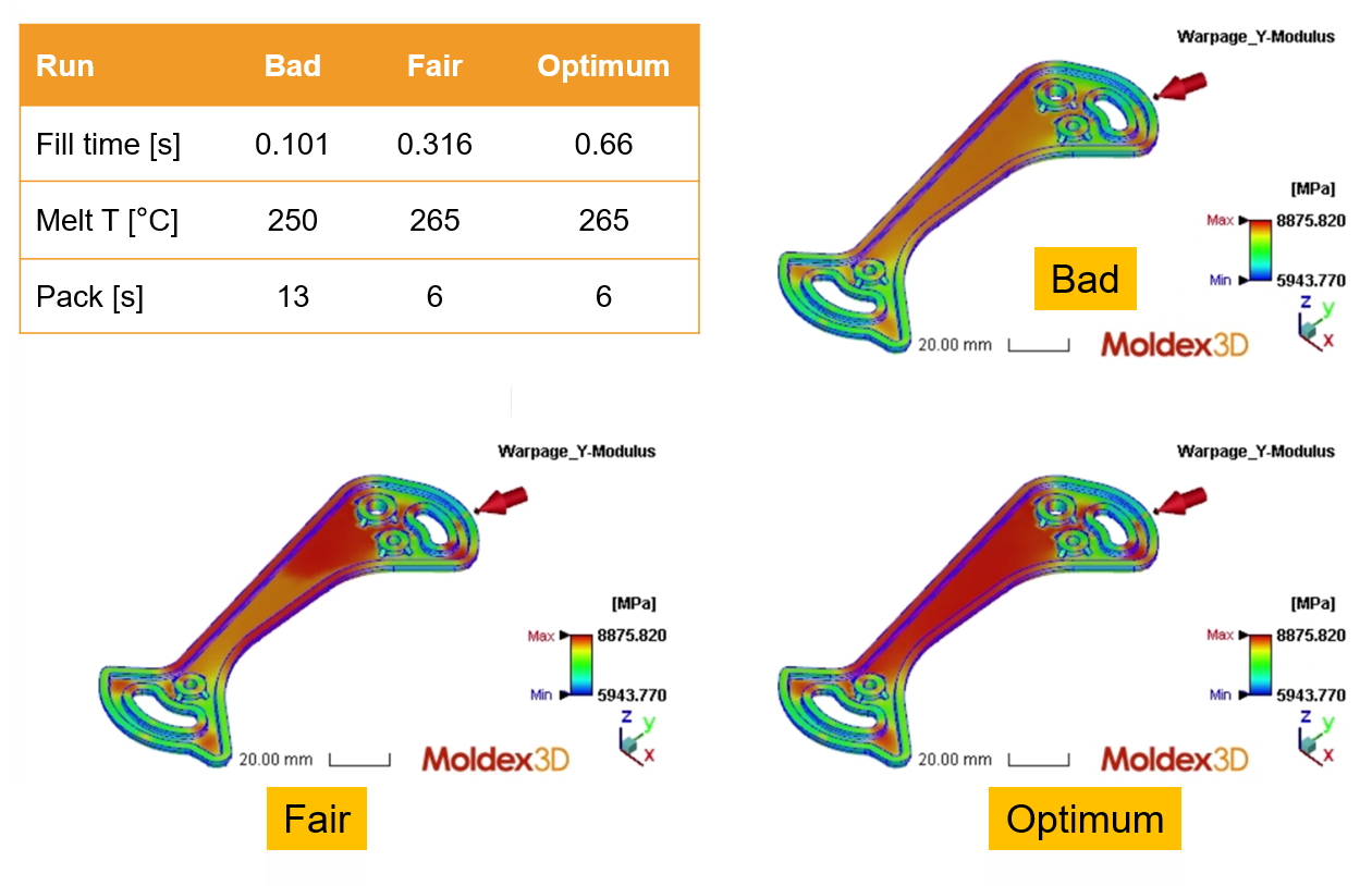
Fig 5. Optimizing elastic modulus by adjusting process parameters
They also evaluated three compounds characterized by different fiber contents to tune the mechanical properties. A structural model was developed to analyze the stiffness of the part. The orthotropic material model was exported from Moldex3D and input in the structural model. The part performance was evaluated considering the force-to-weight ratio. The redesigned part shows higher force-to-weight ratio compared to the original metal parts (Fig. 6).
| Force [N] | Force/Weight [N/g] | ||
| Top Gate | 20.7 | 0.55 | |
| Bottom Gate | 20.7 | 0.55 | |
| Center Gate | 21.0 | 0.55 | |
| Aluminum | 43.3 | 0.74 | |
| Steel | 40.0 | 0.62 | |
Fig 6. Structural results
Increasing in nominal wall thickness resulted in significant improvement of stiffness. The team found 3 mm was the optimum thickness based on the force-to-weight ratio. Longitudinal and cross rib designs also greatly improved the force reaction. Comparing the designs without ribs, with longitudinal ribs and with cross ribs, they found the longitudinal rib the optimum, triggering a high fiber orientation along the ribs. Greater fiber content allowed for comparable stiffness to the steel and aluminum parts (Fig. 7~10).
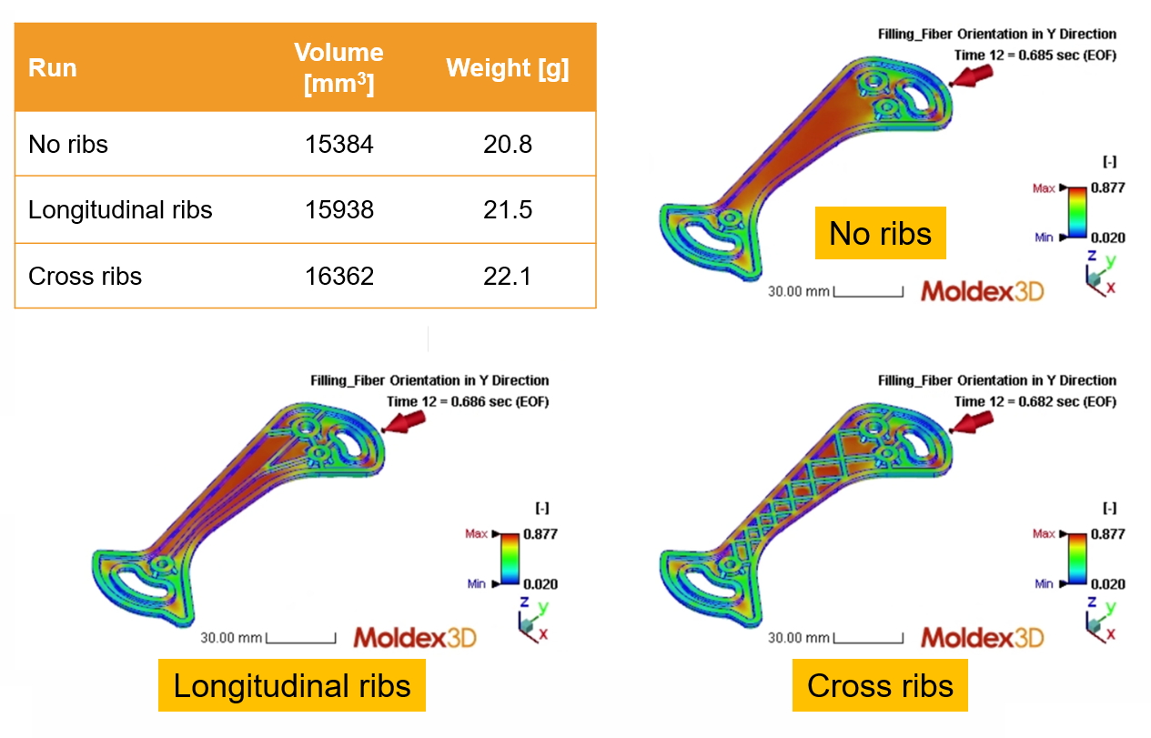
Fig 7. Fiber orientation results of the original and revised designs
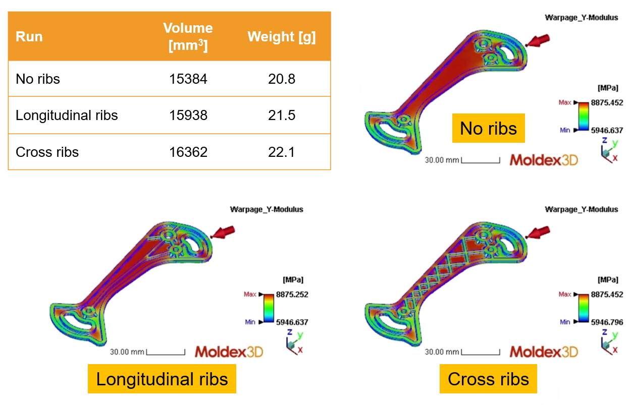
Fig 8. Elastic modulus results of the original and revised designs
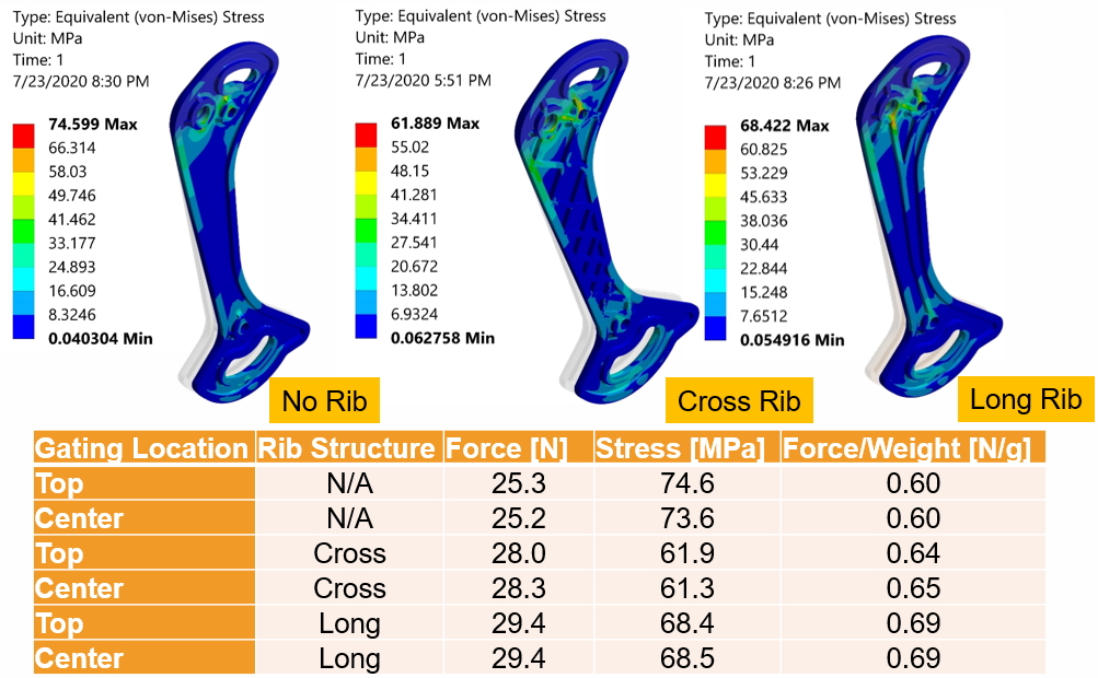
Fig 9. Structural results of the revised design: influence of ribs
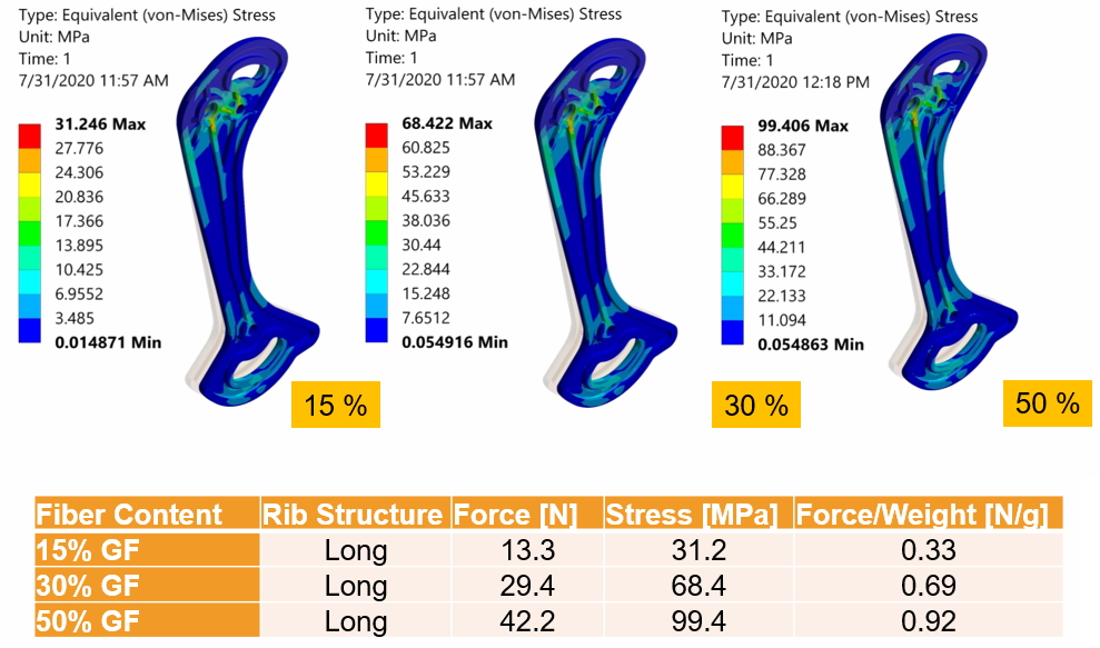
Fig 10. Structural results of the revised design: influence of fiber content
As a result, they decided the best design was 3 mm with longitudinal ribs and 30% fiber content. The detailed optimized designs and process parameters are shown in Fig. 10 & 11.
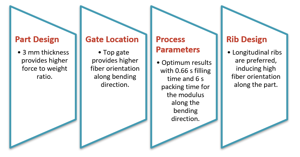
Fig 10. Part and process design using Moldex3D
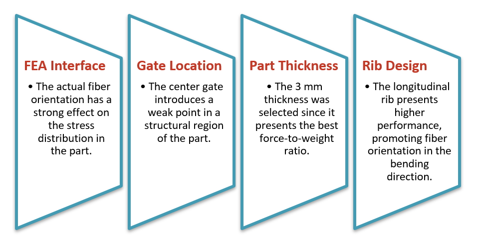
Fig 11. FEA Interface & structural evaluations
Results
Using Moldex3D and the Design of Experiment tools, the UMass team was able to explore and compare many design iterations at a low cost. The mechanical properties of a fiber-reinforced thermoplastic could be quantified and optimized starting from the fiber orientation results. Moldex3D Warp module helped to explore if the part can be correctly assembled avoiding costly mold design changes. Through the FEA Interface, the process-related material properties could be used to accurately predict the mechanical performance of the designed part. Exporting of the orthotropic material model was extremely helpful for exploring metal replacement solutions, allowing to overcome the complexity of non-isotropic materials properties.