
 |
Albert Hu, Technical Manager at Product Division of CoreTech System (Moldex3D) |
A general plastic product manufacturing process involves many stages including product and structure designs, mold designs, mold tooling and injection molding. If the part design is not appropriate enough, it will cause difficulties for the production in later stages or more communication effort on the design changes and fixing of the part and mold. This article focuses on how, during the plastic product design stage, to utilize CAE simulation to approach the optimal designs, prevent potential problems and ensure a smooth mass production.
There are usually Design for Manufacturing (DFM) inspections in the product design stage. Common DFM items include the shrinkage values of plastic materials, draft angles and whether there are barbs or not. The part thickness, rib, and boss designs as well as engineering tolerances are also suggested. These specification inspections can be completed through CAD features or manual inspection drawings. For instance, although we normally seek a uniform part thickness, when thickness variations are required, it suggest designs as shown in Fig. 1. On the other hand, Fig. 2 & 3 show the suggested designs of ribs, and the suggested boss designs are shown in Fig. 4. However plastic injection molding is a dynamic process so the same plastic material made by different manufacturers and with different models can make big differences in material characteristics. Also, different injection machines have different machine responses, and different engineering conditions will affect product qualities. As the result, the problems still occur in actual manufacturing even with DFM. For example, although we have followed the thickness and rib design suggestions, the final products can still have excessive warpage, low structural strength, surface defects or even incomplete filling and cannot be molded.
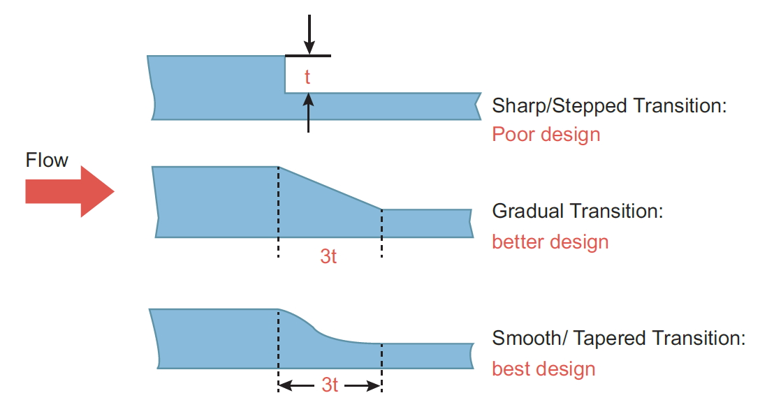
Fig. 1 The suggested designs for thickness variations
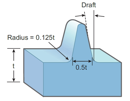
Fig. 2 The suggested rib dimension designs
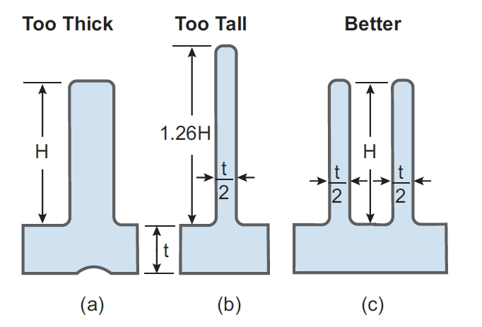
Fig. 3 Equivalent designs of a rib
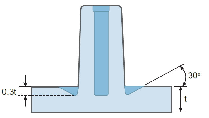
Fig. 4 The boss feature designs with the reference of part thickness
As such, there are no correct rules exactly for all product designs, but a better suggestion to be regarded as the initial design recommendations. Apart from using CAD software to proceed DFM inspections, CAE analysis can further assist to adjust the geometric dimensions, validate the optimized designs, and troubleshoot the issues iteratively. Such iterative design changes and validations are a long-winded process, and ,to overcome this difficulty, Moldex3D SYNC from 2021 supports the geometry optimization tools, helping users greatly simplify the CAE analysis workflow. With this tool, the designs with all the dimension variations and the corresponding CAE analysis results can be completed through several simple steps.
The following case of a connector demonstrates how to utilize Moldex3D SYNC to attain the optimized geometric designs. Fig. 5 shows the original product model that has passed the DFM inspection, and Fig. 6 is its initial simulation result. As shown in the flow analysis, flow imbalance occurs at both sides of the connector. Fig. 7 shows the warpage analysis result, and the warpage will cause a problem for the pin header when it is being inserted, which must be improved before manufacturing. From the cross-section of the original design, both sides have different thickness, and the thicker end should be slightly modified. Although it shows that changing the thickness can improve the flow imbalance and warpage (structural analysis is also required), we cannot determine how much modification is needed to achieve the optimal thickness and it will be very time-consuming to analyze every design with different thickness (Fig. 8). With the geometry optimization tool in Moldex3D SYNC, we can quickly specify the variated parameters and set all the analysis groups and thus attain a set of optimal analysis results (Fig. 9), in which the warpage has been improved while the melt front almost coincides at the end.
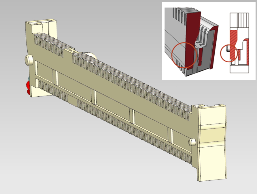
Fig. 5 The connector case and its cross-section
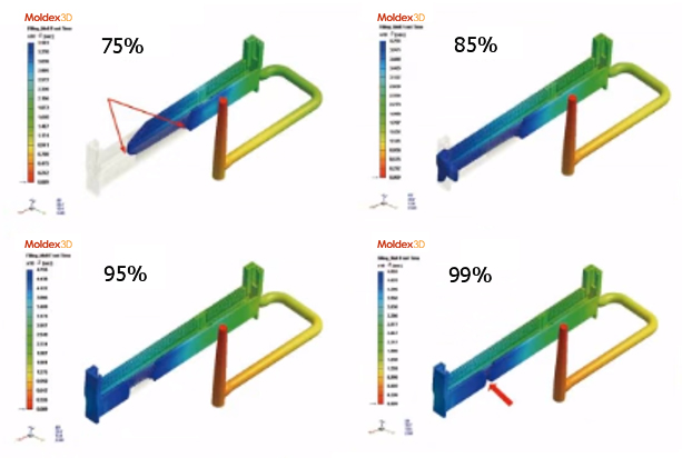
Fig. 6 The CAE analysis results show flow imbalance at both sides.
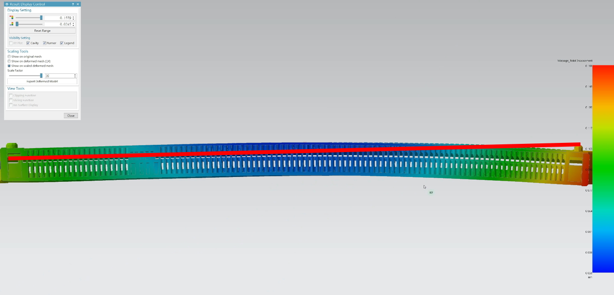
Fig. 7 The warpage deformation caused by flow imbalance
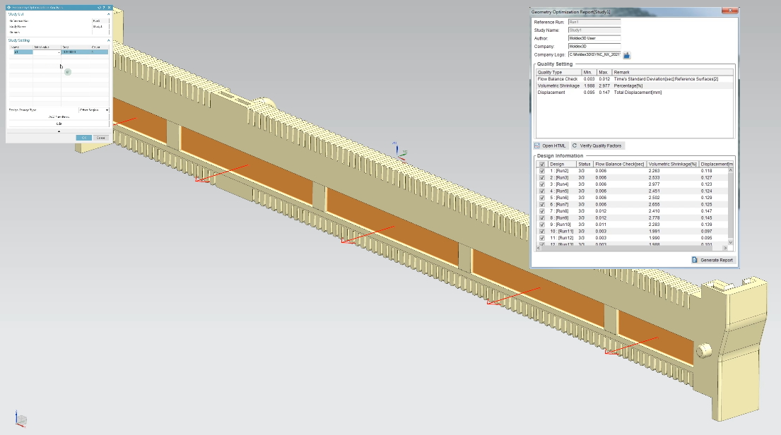
Fig. 8 Setting the variation range of the geometric parameters and generate all the analysis groups at once
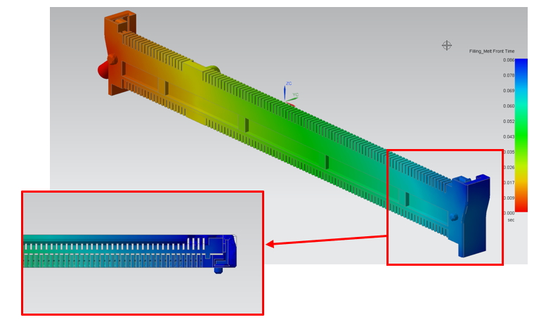
Fig. 9 In one of the analysis sets, the melt front of both sides almost coincides at the end
The example above shows that the static DFM inspections cannot 100% avoid the problems caused by the dynamic manufacturing process, which CAE molding analysis can help; Moldex3D SYNC geometry optimization tool can further simplify the analysis workflow. If we regard the analysis results as a part of the product moldability, the combination of CAD and CAE can effectively enhance the product design efficiency and shorten the time-to-market.