


- Customer: Erteco Rubber & Plastics AB
- Country: Sweden
- Industry: Plastic Material
- Solution: Moldex3D Advanced Package; Flow, Pack, Cool, Warp, Fiber, FEA Interface, MCM
- View PDF Version
Executive Summary
In this case, Erteco was tasked to identify the cause and remove the problem of cracking in a marine propeller inner hub component, which was made from glass-fiber reinforced plastics. The cracks tended to occur while the blades were rotating upon high-load scenarios, which affected the part quality and prevented it from functioning properly.
Challenges
- Part breaks at the connection area when larger engines are used (higher loads)
- High cost solution of applying metal collar to reinforce the area
Solutions
Erteco used Moldex3D to predict critical weld line locations and simulate possible issues when applying a new solution.
Benefits
- Optimized process conditions
- Perfect bonding between reinforcing tape (Ems Tape Technology, ETT) and polymer
- Eliminated crack at the severe weld line location at the thinnest section of the hub
- Huge cost saving by successfully implementing ETT to reinforce the hub
Case Study
The objective of this project was to develop a more cost saving solution to resolve the strength issue on the connection area between the propeller blades and propeller hub as it tends to break upon high load scenarios (Fig. 1). The original solution was costly as the producer, Propulse, had to manually put each part in a turning machine and fit a metal collar around it for reinforcement (Fig. 2).
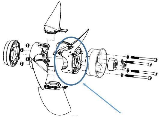
Fig. 1 Exploded view of one of the propeller models from Propulse. The circle indicates the part that is used in this case. (Propulse AB, 2015)
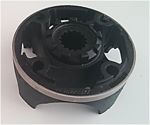
Fig. 2 The steel collar originally used as reinforcement.
The first analysis of the process reveals that the flow patterns in the cavity results in severe weld lines. The weld lines occur at the same position where the blades transfer great load to the hub upon heavy acceleration. This area was the thinnest section, and the weld lines drastically decreased its strength.
Therefore, Erteco decided to apply Ems Tape Technology (ETT) to replace the original solution and utilized Moldex3D to validate this new technology. The sensors are placed in simulation to monitor the temperature and pressure behavior during injection molding. The first test shot showed that the tape was not bound perfectly with the polymer. Thus, Erteco simulated two different scenarios, one of which is with the original setup (Fig. 3) and the other one is with increased mold temperature and melt temperature (Fig. 4).
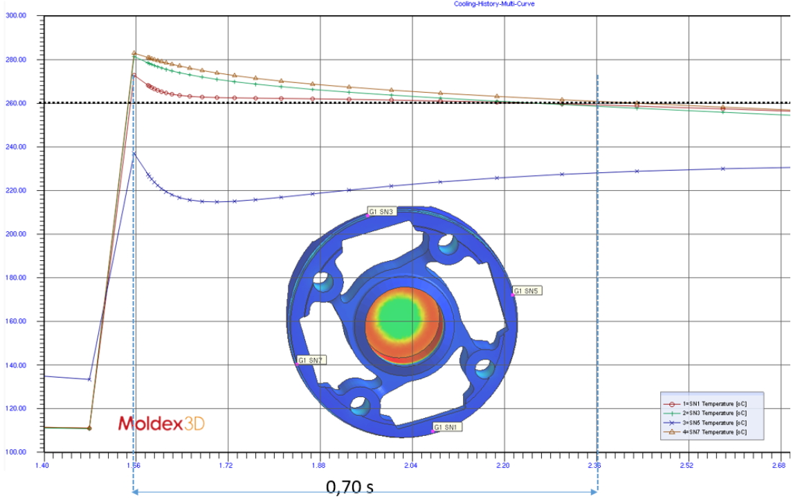
Fig. 3 The simulation case of using EET with the original setup
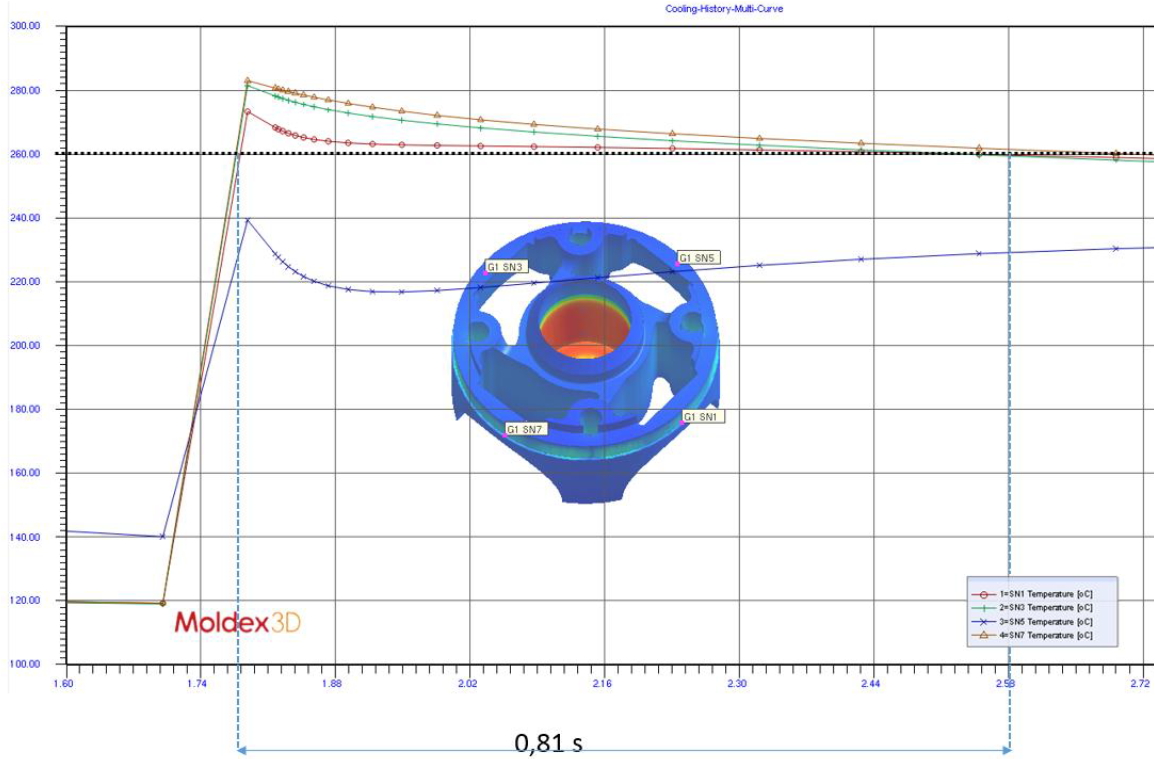
Fig. 4 The simulation case of using EET with increased mold temperature and melt temperature
As a result, Moldex3D helped indicate that an increase in mold temperature and higher packing pressure would neutralize some of the part shrinkage. It can prevent the tape from delaminating from the matrix. This change would increase the time span for the melt front temperature to stay above melting temperature at that weak spot during the packing phase which allows the process to generate perfect bonding between the reinforcing tape and the polymer.
Results
Through the use of Moldex3D, the engineers from Erteco have confirmed the cause of the part quality issues. They could also perform rapid changes to address the issues with a little time and less cost. Erteco would perform further analysis to optimize new solution process conditions to improve quality.