BLM (Boundary Layer Mesh)
Boundary Layer Mesh (BLM) is one of the most suitable mesh technologies for CAE application of plastic injection molding. The parameters for BLM like mesh size, boundary layer count and offset ratio are adjustable individually as needed. The powerful meshing kernel allows users to apply different mesh types for different attributes such as cavity, part insert, runner, and cooling channel. The supported mesh types in BLM are including Tetra and multiple layers BLM. By default, the program will determine a proper mesh size for making surface mesh. A three-layer of prismatic meshes will be generated inward from the surface mesh and then filling up the remaining space with tetrahedral mesh. As result, the solid mesh has minimum seven layers ensured across the thickness direction and can be further increased up to 11 layers for higher accuracy requirements.
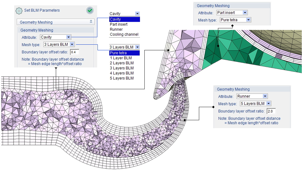
Different BLM Parameter Settings
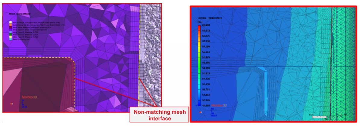
In application of moldbase and MCM (multi-component molding) simulation, the solid mesh nodes on the contact faces between part, part insert and other components are allowed to be unmatched. Non-matching mesh topology is supported for all standard analysis items including flow, pack, cool and warp. Users can thus reduce effort and time in mesh preparation, and the result continuity cross non-matching mesh boundary will be handled by solvers automatically.