

Edited by Jessie Chen Engineer at Technical Support Team, Moldex3D
![]()
- Customer: Felli Co., Ltd.
- Region: Taiwan
- Industry: Industrial Rubber Products Manufacturing
- Solution: Moldex3D Advanced, Flow, Pack, Cool, BLM
Felli Co., Ltd. was Established in 1985 and is the premier manufacturer and exporter of high-quality acrylic merchandise. Known as an innovative designer and producer of consumer and industrial products, the vast product portfolio includes storage containers, kitchenware, bathroom fixtures and pet accessories. Additionally, the company actively operates a diversified product line. Positioning “high, medium and low” products, Felli Co., Ltd. utilizes promotional products and invention patent products to create their marketing advantages. The company’s high-quality manufacturing technology combines three competitive advantages: design, marketing, manufacturing. Using intelligent manufacturing as the foresight, the company gradually implements the development target of achieving “stable equipment, standard process, accurate production, and intelligent manufacturing.” (Source)
Executive Summary
This study was done for consumer household use in the production of easy-to-pick cans. As shown in Figure 1, the main function is a food storage container for consumables or other raw materials. Because the product is long and narrow, the structure and rigidity of the core mold is determined by the geometry. During the injection process, the mold wall is easy to deform from the phenomenon of internal mold pressure, causing core mold deflection and core shift. This product’s hot runner system causes flow imbalance, which leads to serious problems such as air traps and weld lines. Felli Co., Ltd. uses Moldex3D in this study to optimize mold quality design and the injection molding process. This helps in improving the molding defects caused by the problem of narrow and long geometry, as well as enhancing the stability of production capacity and quality.
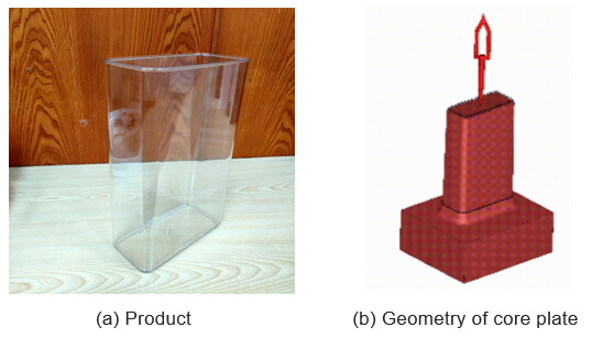
Fig 1. Easy-to-pick can
Challenges
- Improve product defects of air trap and weld line
- Reduce core shift on the mold features
Solution
Felli Co., Ltd. uses Moldex3D Advanced and the Core Shift module to perform fluid-structure interaction (FSI) analysis, then diagnoses the problem of core-side displacement. They use the valve gate hot runner to improve flow balance, and they make design adjustments such as changing product thickness, cavity and core plate temperature to enhance the weld line and optimize the flow balance problem.
Benefit
- Effectively optimize the flow balance and control the core shift problems
- Eliminate weld lines to prevent product breakage
- Meet the product’s appearance quality requirements
- Production yield increased from 0% to 99.7%
Case study
The main purpose of this case is to observe the effect of different hot runner types on flow balance and the deflection effect of the core plate by using molding analysis. Additionally, the influence of mold steel and temperature difference between the direct and reversed operating sides on the deflection effect will be observed. The aim is to evaluate the differences to find out the optimal combination of parameters to overcome potential defects caused by the long and narrow geometry. In the first part, it can be observed from Fig 3., that the two types of hot runner will cause flow imbalance through the corner temperature effect. The Type A single-flow valve gate has different temperature distribution on the inner and outer sections, leading to a corner temperature effect in the runner. The Type B dual-flow valve gate can improve the flow balance.
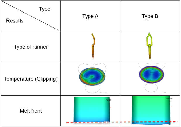
Fig 3. Comparison of temperature and melt front for different types of hot runners
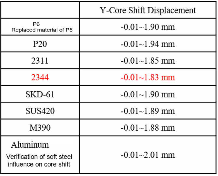
In the second part, to solve the deflection phenomenon of the core side, the effects of mold steel and mold temperature on the core shift are respectively observed. As shown in Table 1, through the analysis results of material and flow balance of the core plate, result of 2234 material is the best flow balance the flow difference trends to be obvious after 80%, and internal pressure difference occurs between the inner and outer sides of the mold cavity, as shown in Figure 4.
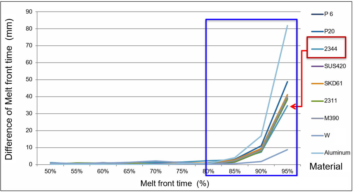
Fig 4. Analysis of material and flow balance of core plate
Table 1. Deflection of different mold steel and core shift
As shown in Fig 5, the core side is adjusted within 0.08 mm in the Y direction using a gasket. The adjustment leads to a variation in the thickness of the original model. As depicted in Fig 6, when the original state is not offset, the air trap is located in the middle position in the +Y direction. When the core side is displaced by -0.08mm, the air trap moves to the -Y direction. The displacement results an increase in weld line meet angle, which improves the air trap situation and controls the deflection of the core side.
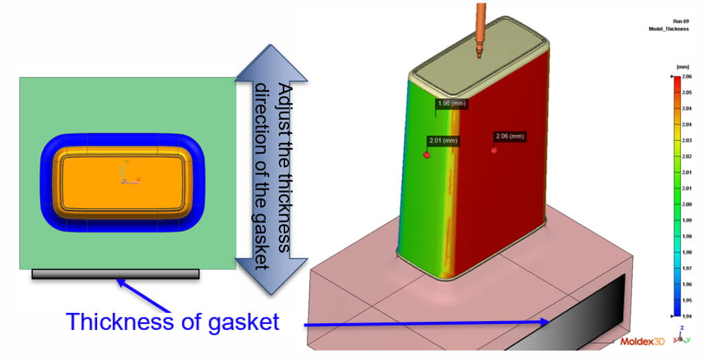
Fig 5. The core plate is translated in the -Y direction
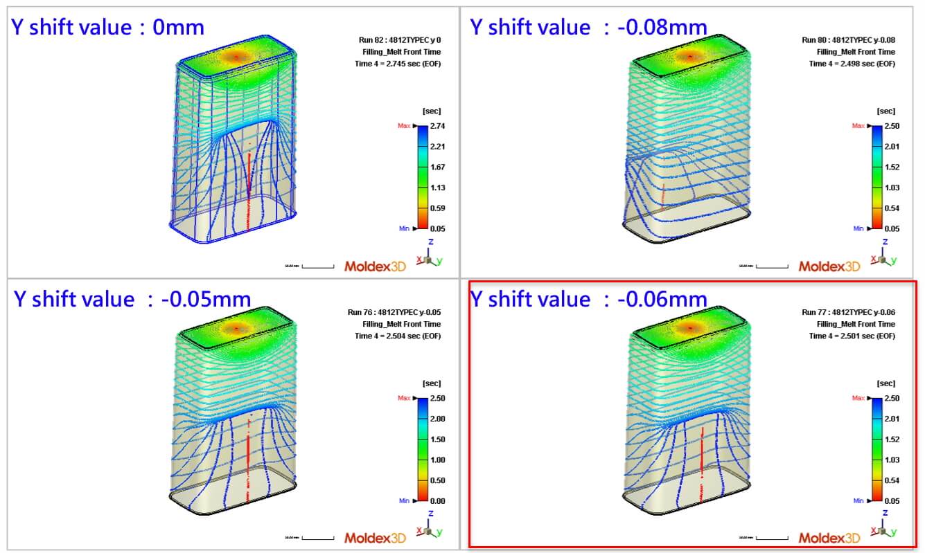 Fig 6. The influence of the core shift on the flow results
In the mold design stage, to observe the impact of adjusting the temperature difference between the direct and reversed operation sides on core shift, the cooling channels on both sides of the mold is set as a separate circulation (as shown in Figure 7), allowing independent control of the mold temperature on both sides. The original mold temperature on both sides was set to 50°C. By adjusting the temperature on direct and reversed operation sides, it was observed that when temperature on the operation side was 40°C and temperature on the opposite side was 49.9°C, the melt front was significantly improved, solving the problem of air trap, as shown in Fig 8.
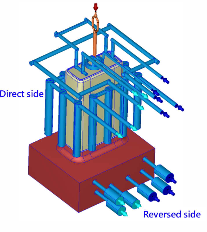 Fig 7. Design of cooling channel
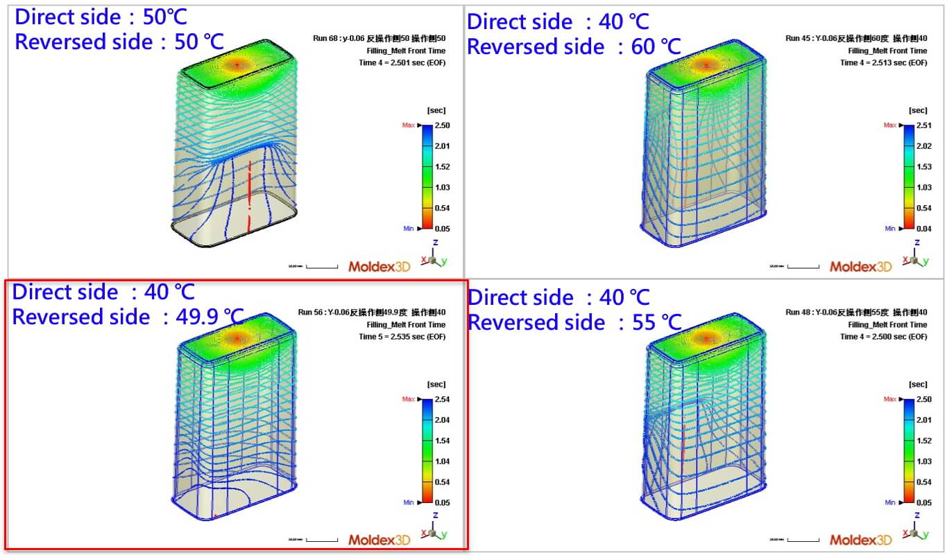 Fig 8. The influence of the core shift is 0.06 mm and the mold temperature control on the flow results
According to the results regarding the influence of hot runner type, mold steel, core shift and the temperature differences between direct and reversed operating sides on the melt front, air trap, weld line and deflection of core side. As shown in the figure 9(a), the finished product that had not been tested before product defect diagnosis exhibits severe mold release marks, weld lines and air trap caused by the deflection of the mold. However, by utilizing Moldex3D, the cause of the defect can be diagnosed, and the best parameters can be identified. The best parameters for this study include a bidirectional hot runner system, core shift of 0.06 mm, the direct operating side temperature of 35 °C, and reversed operating side of 70 °C, which successfully meet the target for mass production conditions, as shown in Figure 9(b).
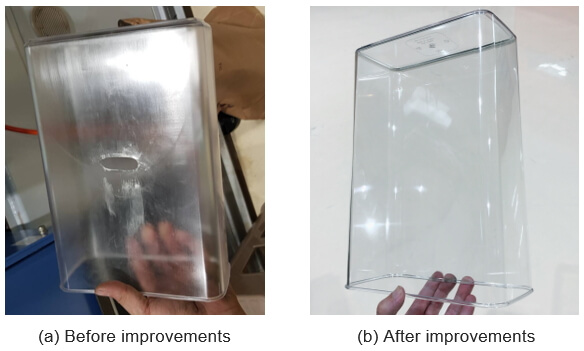
Fig 9. The quality of products after improvements has been greatly improved
Result
Felli Co., Ltd. utilizes Moldex3D’s analysis to grasp the influential factors affecting the molding process, which include mold steel material, core shift, and control of temperature differences between the direct and reversed operation sides. By understanding the plastic flow conditions, the company determines the optimal runner design, and adjusts the process parameters in the most appropriate and efficient manner. Ultimately, this achieves the elimination of air traps, weld lines, and meets the requirements for product appearance quality, resulting in a significant improvement in the molding production yield, from 0% to 99.7% (0.3% defects attributed to other factors), with the goal of achieving stable and continuous 24-hour production.
Thus, through the powerful analysis module of Moldex3D, the integration of materials, mold design, and molding parameters allows for effective defect prediction and formulation of adjustment strategies, reducing development time and the number of mold modifications, leading to substantial cost savings in the development process.