
Edited by Jasmine Ho, Engineer at Technical Support Team, Moldex3D

- Customer: NetShape / Shape Corp
- Country: India
- Industry: Automotive
- Solution: Moldex3D Professional, Designer BLM, Fiber
Shape Corp. is a global leader in impact energy management systems that protect occupants, pedestrians, and vehicles. Headquartered in Grand Haven, Michigan, USA, Shape Corp. is a full-service supplier providing design, engineering, testing, and manufacturing for plastic and metal solutions in North America, Europe and Asia. (Source)
Summary
For the weight reduction needs of automotive parts, the automotive industry has replaced most steel parts with plastic parts. The main issue of a manufactured plastic part is warpage caused by the part size and thickness. In this case, Shape’s method of redesigning the part to reduce warpage is based on the reverse deformation technique. Moldex3D solutions enable them to predict and solve warpage by exporting the inverse model from the software so that tool makers can compensate for unavoidable distortion in the mold, and the part is shown in Fig. 1.
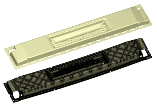
Fig. 1 The automotive car roof cartridge part
Challenges
- To reduce the warpage within the gap and flush tolerance for part assembly
- The warpage of the geometry feature was around 15 to 18 mm which was unacceptable.
Solutions
Due to limitation in part modifications, Shape had very limited scope to reduce warpage. Hence, Shape chose to pre-warp the part to reduce the overall warpage.
Benefits
- Reduced the machine tonnage
- Avoided the fitment issue
- Reduced warpage
- Improved the overall productivity
Case Study
The main purpose of this case was to solve the warpage problem of the car roof cartridge part. This product has specific requirements on the dimensional accuracy of the finished product, and multiple positions need to be assembled with other parts (Fig. 2).
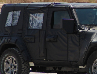
Fig. 2 The finished assembled product
First, in the original design, the warpage at the Z-displacement showed a positive warpage of about 8 mm and a negative warpage of about 14 mm. The warpage at the total displacement was shown to be about 2.52 to 15.20 mm (Fig. 3). Through the output simulation warpage model for cross-validation in Rhino, the distance between the original CAD model and the simulated product warpage model was about 14.35 mm, as shown in Fig. 4.
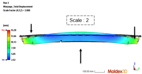
Fig. 3 The total displacement of the original design
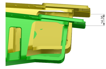
Fig. 4 Comparison of the original CAD model and simulated warped model
Secondly, according to the warpage analysis results of Moldex3D, the mold compensation was performed with the reverse warpage method, and the geometric design was changed to correct the warpage problem. The process was as follows: Export the deformed model in Moldex3D, convert the STL file to STEP file in the Inceptra software, and then reverse the warping direction in Inceptra and export the model, as shown in Fig. 5. Next, perform simulation in Moldex3D with the same process conditions.
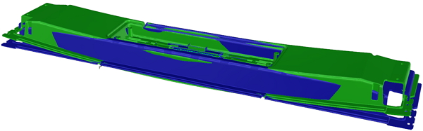
Fig. 5 Green: the warp model from Moldex3D; blue: the opposite warp model from simulation
The analysis results of the opposite warp model are shown in Fig.6. The warpage at the total displacement is shown to be about 2.19 to 12.85mm, which is similar to the original part/prototype trial.
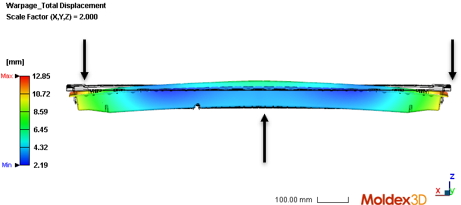
Fig. 6 The total displacement of the opposite warp model
Finally, through the model output, the Shape team stacked the original and opposite warp models before and after warping, as shown in Fig. 7. The yellow represents the original part model, the green represents the warp model from the simulation, the blue represents the opposite warp model for simulation, and the magenta represents the pre-warped part after simulation. The actual molding also successfully used the pre-warp technology to solve the warpage problem of the product, reducing the warpage from 18 mm to 3 mm as shown in Fig. 8.
In addition, Fig. 9 shows the comparison between the simulation and the actual product. As shown, the air trap and melt front between the actual part and simulation results are highly similar.
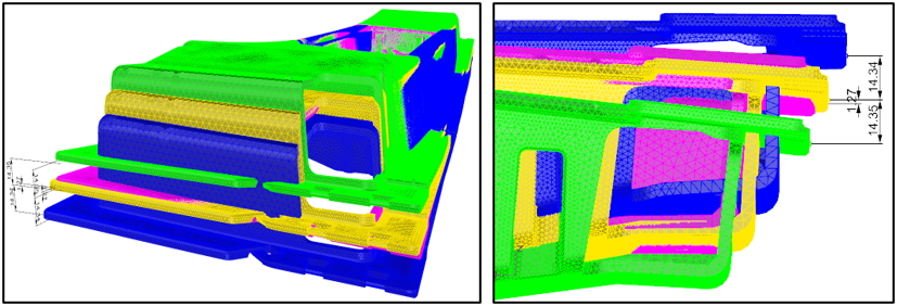
Fig. 7 The model comparison between the original part and reversely warped parts
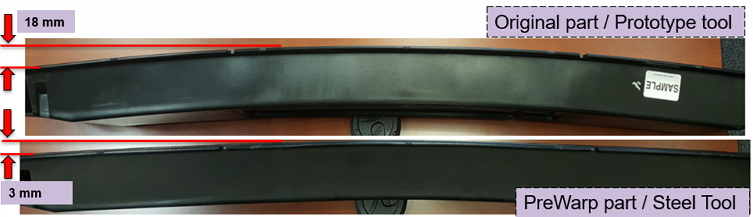
Fig. 8 Warpage comparison between the original design and the pre-warped design
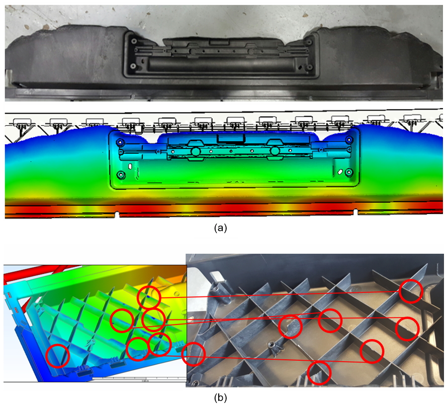
Fig. 9 The comparison of the simulated and actual product: (a) flow front; (b) air trap.
Results
Moldex3D helped Shape Corp. detect the part’s warpage, and through the study, they successfully reduced the overall warpage and met the acceptable design standard. Thus, they were able to produce qualified parts in the first trial (T0) and reduce considerable time and costs generated by the rework of molds and tools.