
Jill Chen, Deputy Administrator at R&D Division, Moldex3D
For both performance and efficiency, CAE teams will face lots of challenges during the IC packaging process analysis. For example, preparing a structural mesh model for a simulation project is usually very complex and time-consuming. In general, one must first import a 2D (or 3D) image file, then construct the base mesh as well as a hybrid solid mesh. After checking the meshes for quality and accuracy, settings for different elements, like chip, die, etc. need to be modified. After the creation of a solid mesh for a unit is completed, it is necessary to create a complete package model according to the strip design and by copying the entity mesh. After that, the establishment of solid meshes such as runner and the setting of boundary conditions need to be performed outside the model to complete the mesh processing of a packaging process analysis. After the mesh processing is completed, a project needs to be created. The steps are as follows: first, create a new project; then establish an analysis process, including setting meshes, materials, molding conditions, etc., and then set the analysis sequence. Until these are completed, a large number of analysis processes are carried out, and the analysis results can be viewed in the end.
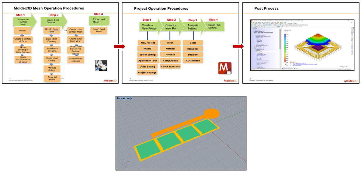
Image 1 The IC packaging process of the past
The complex modeling process often takes many days and a lot of effort. Therefore, for a CAE engineer and the entire management team, it may cause unavoidable pain points:
- Spending too much time on routine operation
Any Design in the modeling process requires repetition of certain workflows and operations. For example: constructing solid meshes. - Difficult to run analysis for all designs
During the process of analysis runs, it requires a CAE engineer to manipulate. This makes it difficult to conduct a complete analysis of all the packaging designs within the enterprise, so the potential design problems sometimes can’t be discovered immediately. To make a complete analysis of all the packaging designs within the enterprise, it needs a huge CAE work team, which is impractical for the operation and management of the enterprise. - The waste of human resources
The typical IC packaging process often requires significant amount of manual labor in the analysis operation. Undoubtedly, this is a waste of human resources, and it severely undervalues the importance of CAE engineers.
Therefore, in order to avoid wasting time, effort and human resources, as well as to improve the completeness and accuracy of all steps of the IC packaging process, iSLM provides an automated IC packaging workflow. By pre-determining a series of standard parameters and databases, this not only continues the spirit of high standardization of the IC packaging industry, but also simplifies the development process. This accomplishes automation of IC packaging and simulation of analysis workflow furthermore. The above-mentioned standardization includes a unified definition of design layers names, runner designs, mold parameters, etc., which seemingly is inflexible, but helps automating the workflow. In iSLM, you can upload the 2D design file (.dxf), and then set the geometry of each object layer as well as the material parameters. After filling in the setting of process conditions, the analysis can start. When analysis is completed, relevant results can be viewed on the 3D viewer platform. The entire process, from importing models, automatically generating meshes, setting molding parameters to complete analysis, are all done on the iSLM platform.
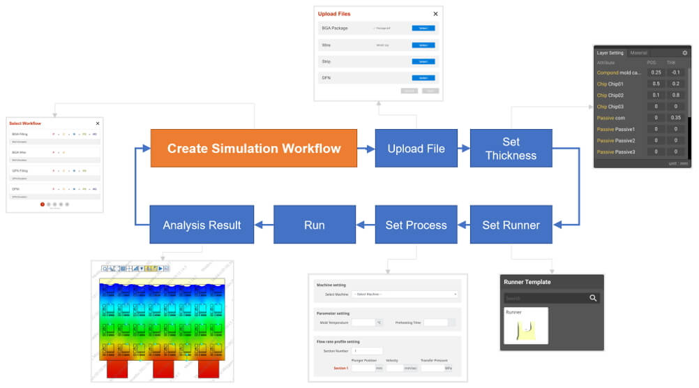
Image 2 Graph of the IC packaging process workflow on the iSLM platform
On the other hand, in order to better align with the core concept of automation, Moldex3D iSLM also provides another analysis workflow setting, which is the ” IC Simulation and Packaging Analysis Automation Workflow ” This process first establishes the standardized steps of unified channel design, model parameters, etc. in a customized file template. Users only need to upload 2D design files (.dxf) and corresponding worksheets data files (.xlsx) or JSON files according to the template format in the project. The system will automatically read and transfer the uploaded file contents to complete the automated simulation analysis work. This greatly reduces the consumption of human resources and elevates the standardized setting process to a customized, automated level.
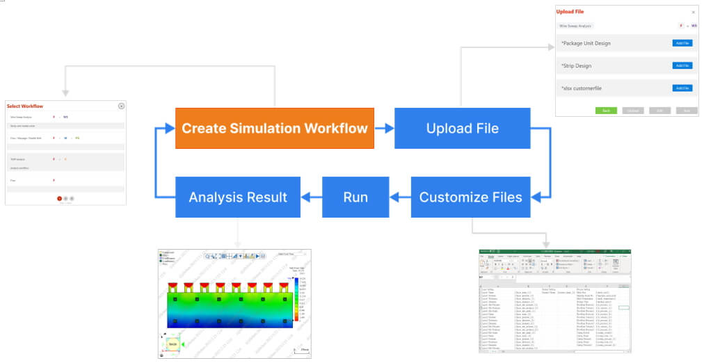
Image 3 Automated workflow diagram for IC packaging analysis on iSLM platform
In the 3D viewer, besides zoom in / out and rotate the 3D object, users can also use the toolbar to view weld lines and packaging defects after the analysis. In addition, if one wants to check gate positions, selecting the ” Gate ” button will reveal related gate information. In the drop-down menu at the top right, there are also a lot of items for viewing, such as pressure, maximum temperature, etc. If the ” Wire Sweep ” option is selected in the menu, the ” Single Package Viewer ” and the model will appear. The coordinate diagram in this panel provides the function of viewing a single object. Click the download button to download the object file to the computer in two formats, csv and dxf. On top of that, iSLM also provides melt front animation, XY curve graph and other various result data to view the results conveniently.
Image 4 Check results on iSLM 3D Viewer
Through the simplified and standardized modeling process of IC encapsulation analysis simulation workflow in iSLM helps reduce the large amount of effort and time spent on routine tasks. By automating the construction of meshes and other data, as well as scheduling each analysis process, it not only saves time on operating, but also highlights the value of mold flow analysis and CAE team.