

Edited by Yoganantham Natrayan, Engineer at Technical Support Team, Moldex3D

- Customer: Toyota Research Institute North America
- Country: USA
- Industry: Automobile
- Solution: Moldex3D Advanced Package; Moldex3D Compression Molding Module, Flow, Fiber, Warp, FEA Interface
The Toyota Research Institute, North America (TRINA), founded in 2008. Whether it is biologically-inspired paint, R&D 100 Award-winning cooling technology for hybrid vehicle electronics, next-generation batteries based on magnesium, or cars that drive themselves, the innovations introduced by these leaders show that TRINA is not just keeping pace – it’s helping to set the pace. (Source)
Executive Summary
Since there’s no practical commercial software available to handle the compression molding of the sheet materials, Toyota Research Institute of North America (TRINA) team aimed to develop a design method for mold filling analysis and warpage analysis of the CFRP composite made from discontinuous long fibers in sheet format. In this project, a novel, two-step CAE method was developed to simulate the compression molding of sheet materials. The two-step method combined the use of LS-DYNA and Moldex3D to satisfy the need to capture the elastic-plastic structural behavior during draping and the flow behavior of resin melts during compression, enabling TRINA to better predict fiber orientation and warpage.
Challenges
- There was no practical commercial software can handle the compression molding of the sheet materials made from non-woven fibers
- None of the standard structural mechanical or compression molding software can handle the draping of the sheet
Solutions
The compression molding simulation was carried out using the proposed two-step approach. First, the sheet materials were simulated as a draping process using LS-DYNA. Next, the draped shape was used in Moldex3D compression molding simulation.
Benefits
- Allowed manufacturers to simulate draping and compression molding of sheet materials with a two-step CAE method, which is previously unavailable
- Obtained accurate fiber orientation prediction of CFRP parts
- Accelerated product development and reduce costs
Case Study
In this case, the Toyota Research Institute of North America (TRINA) researcher was interested in the thermoplastics with carbon fiber in the form of sheet molding compound (SMC) to manufacture a part. The sheet charge made of discontinues long fiber in the sheet format. TRINA researcher preferred sheet charge due to its better possibilities of initial long fiber structure maintaining after the compression molding process completed. This process followed by four steps as shown in Fig. 1:
Step 1: PA6 with 35% of the carbon fiber sheet charge was heated up to melt temperature.
Step 2: The heated sheet material was draped into the cavity by with low pressure called draping.
Step 3: Compress the sheet into the cavity and hole at high pressure until the solidification.
Step 4: The solidified part was ejected from the mold and cooled in an open-air.
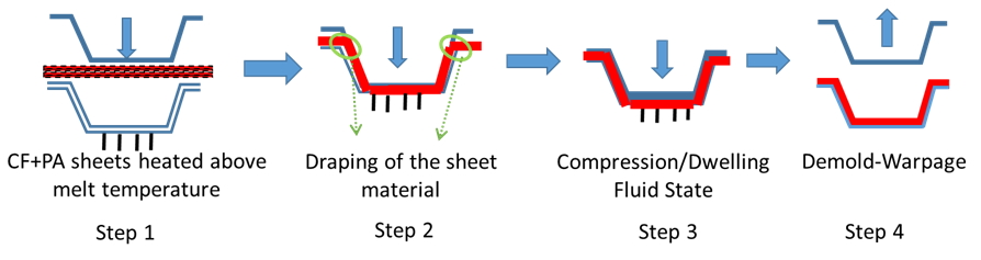
Fig. 1 Compression molding process using the sheet charge
Sheet material compression molding process usually companies draping and compression process. Draping involves elastic-plastic structural behaviors and the compression process involves flow behavior. To integrate the two behaviors in the simulation can be a big challenge. Moldex3D allows the freedom for users to integrate with other structural simulation software to comprehensively simulate the two behaviors. The sheet material compression molding simulation includes two steps as shown in Fig. 2. In the first step, the draping analysis is done using explicit finite element analysis (LS-DYNA). In the second step, the filling and warpage analysis are done by using Moldex3D Compression Molding Module.
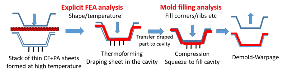
Fig. 2 The simulation approach used for sheet material in compression molding.
Based on the needs of lightweight components for the automobile industry, the TRINA researchers designed the three-cavity part (Fig. 3). The measured material properties imported into the Moldex3D is shown in Fig. 4.
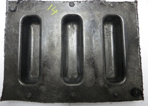
Fig. 3 The manufactured part
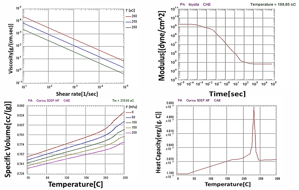
Fig. 4 The measured material properties imported into the Moldex3D format.
TRINA researchers did the experiments to validate the integration simulation results of warpage and fiber orientation. In LS-DYNA, the draping distance stops at 60%, 80%, and 100% of the compression zone, and these boundary conditions were used as a prepreg for Moldex3D. The simulation results show that when the draping distance stops at 80%, showing good agreements results with the experimental data (Fig. 5), so the subsequent analysis will be conducted under this condition.
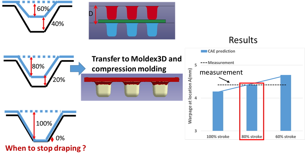
Fig. 5 Validation of stroke distance effects.
The comparison of warpage results is shown in Fig. 6. The warpage is measured at location A in the simulation model and the experiment. The warpage based on different mold temperature is predicted under 8% of error. In addition, increasing the mold temperature leads to increasing warpage observed from both experiment and Moldex3D.
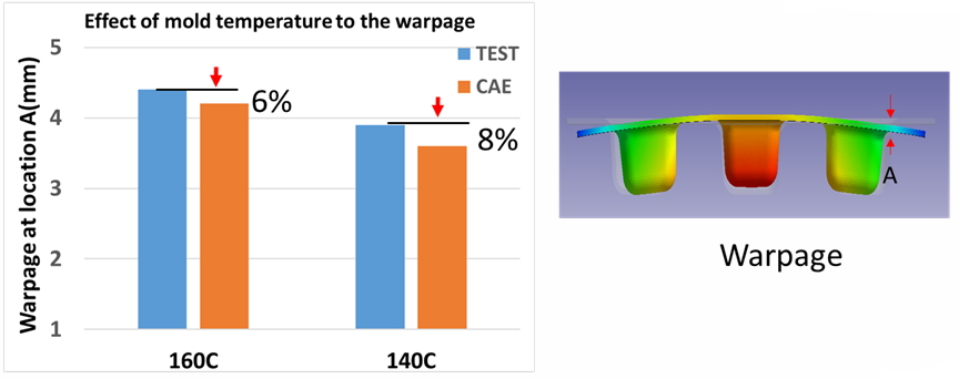
Fig. 6 Validation of warpage results
To validate the fiber orientation effect from the experiment and simulation, the TRINA team chose the locations of A, B, and C for validation as shown in Fig. 7(a). The experimental fiber orientation in the locations above measured through the computed tomography and volume graphics analysis method. The comparison results for CAE and measured from experiments in the normalized thickness showed in Fig. 7 (b), (c), (d). Overall, the Moldex3D predicted data was within 15% of accuracy criterion.
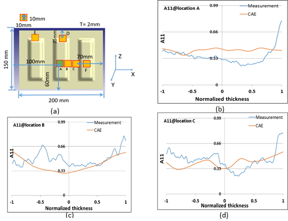
Fig. 7 Validation of fiber orientations.
Results
With the integration freedom of Moldex3D with other structural software, TRINA was able to use the new novel two-step approach method to simulate the compression molding process of discontinuous long fiber sheet. TRINA can also obtain the best-agreed prediction result with small error discrepancy. TRINA now can achieve/increase the production of lightweight composite with high strength products for the automobile industry.