
With the growing demand for lightweight designs and composite material applications, part designers and engineers across different industries had been challenged to search for a more innovative yet economic molding solution to stay competitive while also opening up new opportunities in their industries. Therefore, the conventional solid injection molding process could no longer satisfy the pressing need to reduce overall production cost while maintaining the competitive advantages for most businesses. Thus, MuCell®process, a novel approach to composite injection molding, was introduced.
In MuCell®process, Supercritical Fluid (SCF), usually as nitrogen (N2) or carbon dioxide (CO2), is mixed with polymer melt to create a uniform single-phase solution, and then injected into the mold cavity. The melt flow with bubbles will foam and form a part. The MuCell® Process generally offers a 50-75% improvement in key quality measures, such as flatness, roundness, and warpage, while also eliminating all sink marks. These improvements result from the fact that relatively uniform stress patterns are created in the molded part rather than non-uniform stress characteristics of solid molding. When compared with solid injection molding, MuCell®products rarely have shrinkage problems; the parts that are produced tend to comply far more closely with the mold shape and, presumably, the dimensional specifications of the part itself. In other words, using MuCell® process can help realize the lightweight design concepts with ease without too much compromise on the product mechanical strength.
However, users of MuCell® process often face a difficult task of trying to find a perfect balance between achieving lightweight products and having sufficient mechanical strength of a finished part. As a result, a substantial amount of mold trials using trial-and-error were needed to attain the most optimized processing set-ups and quality finished parts. In order to alleviate the burden of tedious mold trials and provide further simulation insights into the complex MuCell® process for its users, Moldex3D introduces a new module, Micromechanics Interface to connect with nonlinear multi-scale material modeling software to make the simulation workflow more effective and efficient. Combining with structural analysis, nonlinear multi-scale material modeling software, such as Digimat and Converse, provides the capabilities to simulate the composite materials at micro-macro levels and gives users an opportunity to solve complex nonlinear multi-scale finite element problems. With Moldex3D Micromechanics Interface, users can now output the micromechanics properties of the MuCell® process, such as cell size and cell density, to Digimat and Converse, which previously was not available, for further structural performance assessment of MuCell® parts. Hence, the accuracy of the structural analysis of MuCell® parts can be further ensured since the microcellular output is considered and incorporated in the structural computation.
In the following context, we will introduce the application of Moldex3D Micromechanics Interface to Digimat on the MuCell® process simulation.
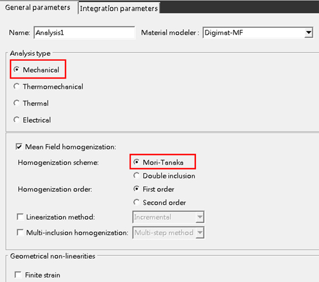
As shown in the figure below, create the material file for Micromechanics analysis in Digimat-MF. Select “Mechanical” as the analysis type, and use Mori-Tanaka Model to calculate the microcellular structure of the MuCell® foam.
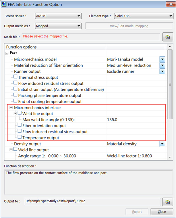
Next, as shown in the figure below, via Moldex3D Micromechanics Interface, users can choose micromechanics data such as material properties, residual stress, etc., that they wish to output to Digimat for structural analysis.
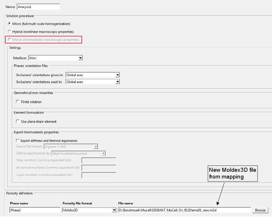
Then, import the material file created in Digimat-MF to Digimat-CAE. Select Marc, the finite element solver as the Interface. Import the result file of micromechanics structure after mapping (as shown below).
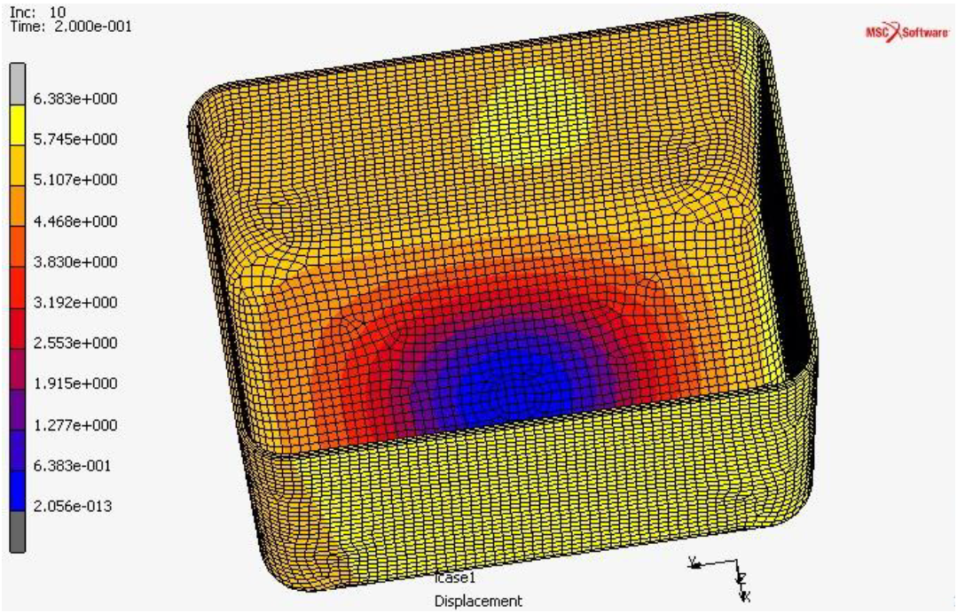
The overall warpage displacement results can be shown in the structural analysis. On the left figure, due to the non-uniformity of the cell size and cell density, we can clearly see the asymmetrical differences in product strength between the left side and the right side of the part. As a comparison, the figure on the right provides a different structural analysis result when the MuCell® process-induced material properties are not included in the structural analysis computation.
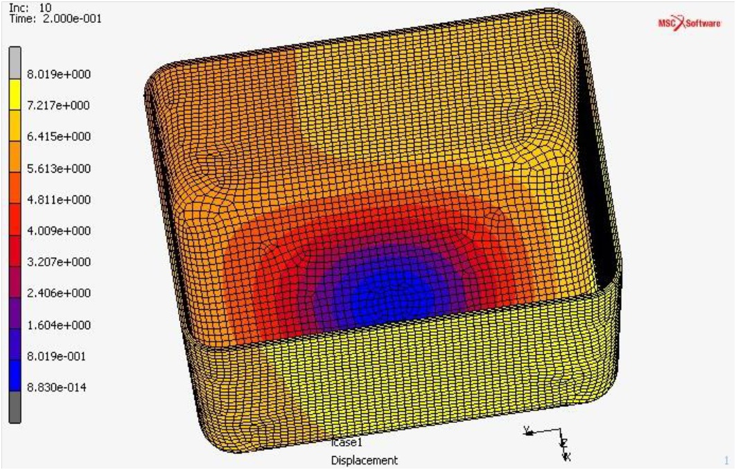 (Left): Due to the non-uniformity of the cell size and density, we can clearly see the asymmetrical differences in product strength between the left side and the right side of the part.
 (Right): A different structural analysis result when the MuCell® process-induced material properties are not included in the structural analysis computation.
In Product Lifecycle Management (PLM), special attention needs to be given to the process-induced properties in the mold-filling analysis in order to get an accurate simulation assessment on product structural analysis. It used to be neglected in the past and it tends to mislead the simulated structure analysis result as the real representation of the final product structural strength.
In reality, the different molding process-induced properties can result in various results of the product structural analyses. In order to help users attain an accurate structural analysis, Moldex3D Micromechanics Interface can successfully connect Moldex3D with nonlinear multi-scale material modeling software like Digimat and Converse. Users can now output the micromechanics properties of MuCell® process, such as cell size and cell density, to Digimat and Converse to attain an accurate structural analysis, thus making PLM more efficient and effective.