- Customer: Shape Corporation
- Country: India, USA, Europe, Asia
- Industry: Automotive
- Solution: Moldex3D eDesign
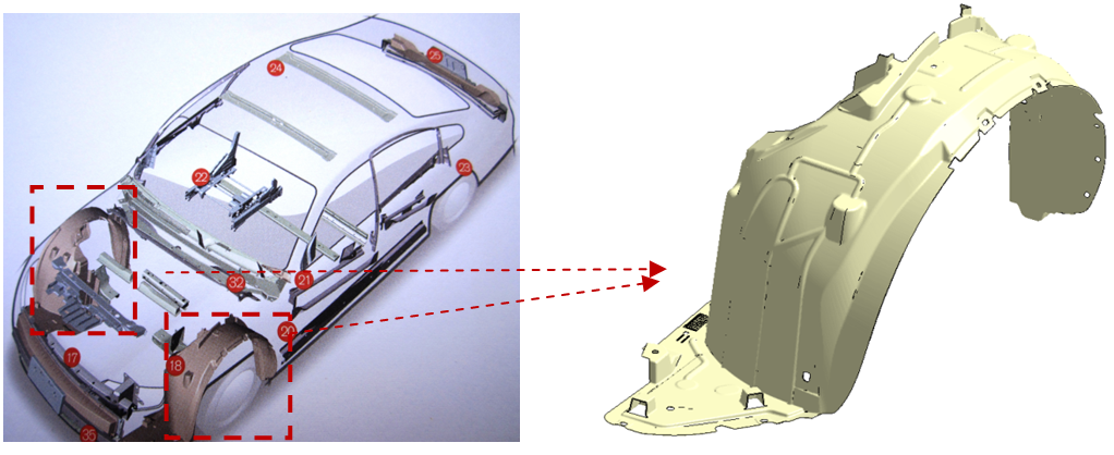 A fender protector fits on top of the wheels of a vehicle, and its function is to protect the vehicle steel inner body from being hit at a high speed and damaged by stones, dust or unwanted items.
Executive Summary
This case features an automotive part: a fender protector. A fender protector is a part widely used in automotive industry for all kinds of vehicles. This part basically fits on top of the wheels of a vehicle, and its function is to protect the vehicle steel inner body from being hit at a high speed and damaged by stones, dust or unwanted items. This fender protector uses valve gated hot runners which are widely used in injection molding to manipulate the flow, timing, location of weld lines and pressure in the cavity. Furthermore, the automotive industry is moving to making thinner and lighter parts for weight reduction yet at the same time trying to make sure the parts still meet durability standards. In this case, there’s a valve gate system along with different thickness of flow leaders, placing them in various areas of the part to optimize the filling pattern, reduce air traps, and reduce tonnage.
In order to simulate this process, the team used a shell mesh to make multiple design changes on the part geometry by adding flow leaders of varying thickness at different locations to minimize the weld line formation and balance the flow pattern throughout the part. After achieving the most optimized filling situation through multiple runs in the Moldex3D software, the modified changes were added back onto the final part geometry; Shape engineering team utilized Moldex3D eDesign to produce a 3D mesh and then compared the final results of shell vs. 3D mesh. As a result, the team found out that Moldex3D shell analysis produced reliable results and helped them make quick design modifications within a short time, and Moldex3D eDesign 3D mesh analysis further helped them verify their final design with accurate, close-to-reality results prior to the actual mold making.
Challenges
There were many challenges encountered while designing the part and the mold:
- Implementing an ideal valve gate design to achieve flow balance
- Adding flow leaders to ensure proper filling while keeping the part weight down to the desirable range
- Lowering the exceeding tonnage required in the original design down to the specified tonnage limit
- Eliminating mold trial counts and avoiding future part and mold re-works
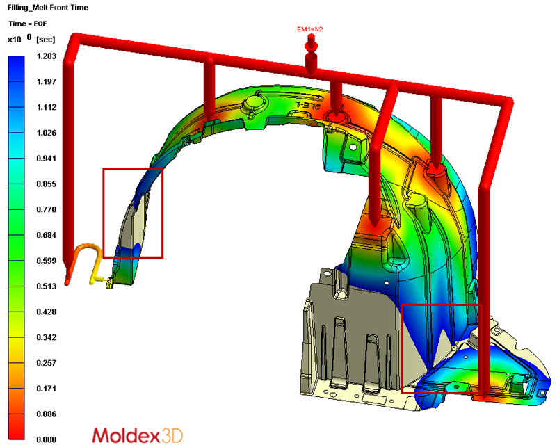
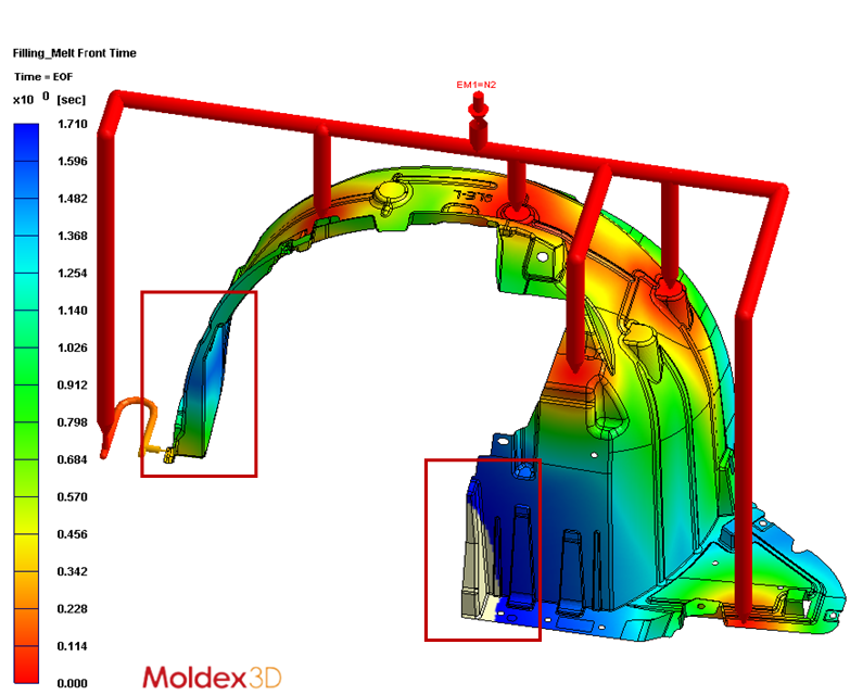
Melt front time-75% Melt front time- 100%
Melt front time-75% (left): Air trap & weld line formation leading to part weakness are highlighted in red. Melt front time-100% (right): The left side of the part is filled earlier than the right side. The right side part indicates a short shot problem.
Solutions
To overcome the challenges and achieve initial goal, it would require multiple iterations on filling simulation, tweaking number of gates, gate locations, flow leader locations, and thickness changes. In addition, this all had to be done quickly due to a short turnaround requirement of 2 weeks for filling simulation. Shape utilized remote computing to construct and simulate a Moldex3D shell mesh analysis, which provided quick simulation results which allowed time for engineering discussion on the next iteration direction. This absolutely helped expedite the workflow and Shape was able to achieve the ideal filling scenario in a short and limited time. Next, Moldex3D eDesign 3D analysis was used to help further verify the final design. That is, the 3D analysis simulation results were proven to be strongly matched with the actual mold trial results.
Case Study
Firstly, Shape ran the simulation with a basic gate location arrangement to get an initial idea of the flow pattern, required pressure and tonnage. They utilized the lower-level mesh option in Moldex3D to speed up the computing time. And along with using their full 8 CPU capacity, they got quick results. Secondly, based on initial analysis runs, Shape started to change the gate location as well as number of gates. It became apparent that due to the tonnage limitation, it would not be possible to achieve ideal filling scenario without adding flow leaders. Each modification of the flow leaders required Shape’s recommendation, approved by both their own engineering team as well as their customer’s.
Moreover, the Shape engineering team faced a rigid constriction on time reduction throughout the whole developing process. Thus, they switched to using the shell modeling which enabled them to attain results more quickly and still have enough time to modify the flow leaders for each of the 20 plus iterations. They modified gate locations, tweaked the flow leader thickness and locations until all the requirements were satisfied. At last, they were able to lower the tonnage required under 2000 tonnage and attained almost simultaneous end-of-fill time on both left and right side of the part with a filling difference in only less than .2 second. In addition, the air traps were controlled within a manageable range, and any post processing was kept in a minimized fashion by only utilizing as few external runners as possible to feed the part.
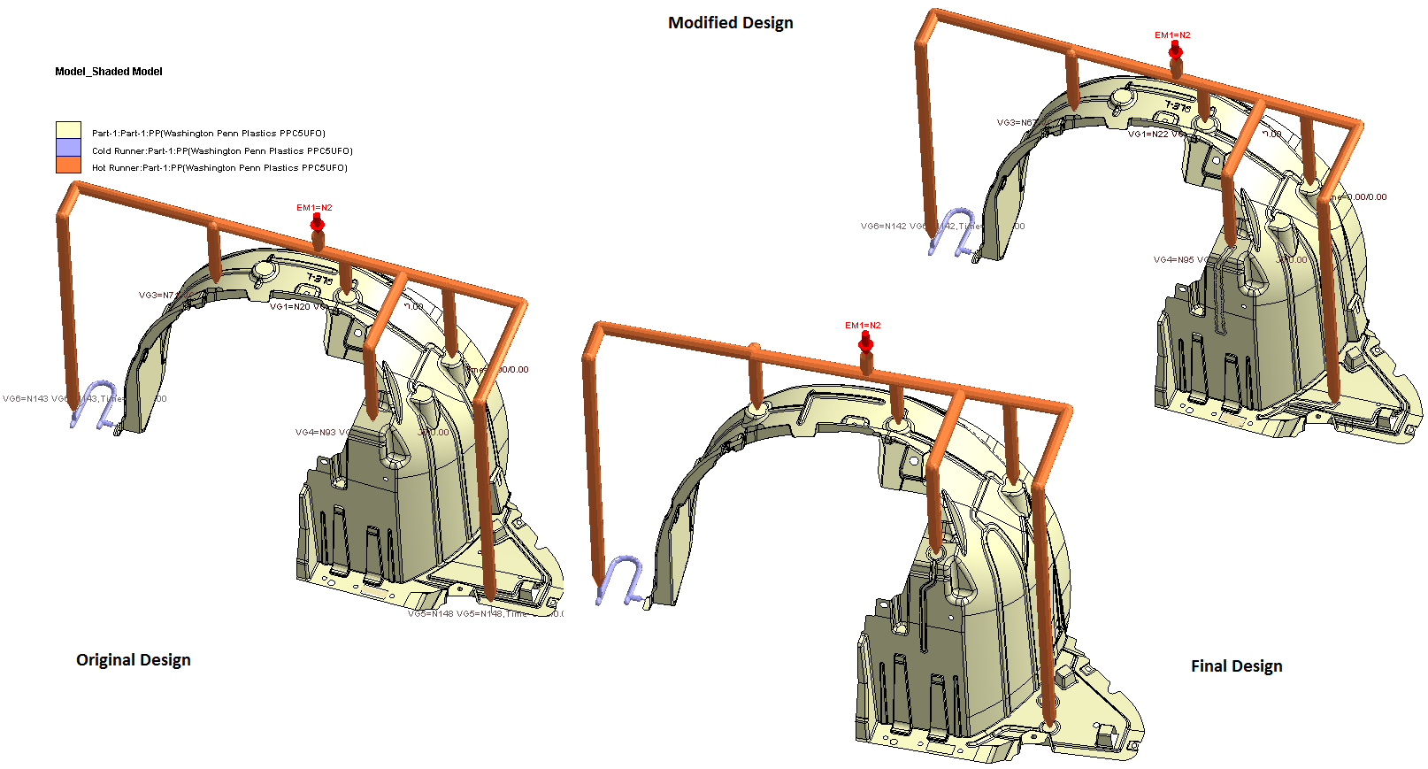 Using Moldex3D Shell mesh, Shape was able to run the analysis for the original part and then make appropriate modifications by adding flow leader and removing & shifting the part profile in a very quick time to achieve the ideal results.
Then, Shape’s engineering team gave the simulation feedback to the part designer in order to modify the final part design. With the final design on hand, the engineering team simulated the final design with Moldex3D eDesign 3D modeling, and cross-checked the results with the original shell model and the actual mold trial results. The simulation results, both the shell and 3D modeling, closely reflected the real-life molding scenario.
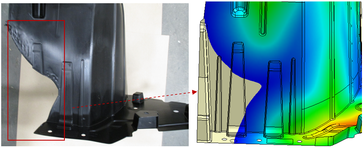
 The simulation analysis results are almost closely matched with
a real-life molding part including flow pattern, pressure, tonnage, etc.
Benefits
Using the Moldex3D Shell and 3D modeling analyses, Shape was able to achieve the desired flow pattern, determine the optimal number of gates and locations, and lower the tonnage required. In this way, Shape successfully avoided spending a significant amount of dollars in potential mold changes or repairs.
| Item | Content |
| Trial Costs | Elimination of approximately 6 mold trials during maturation to determine flow issues discovered by the filling simulation, and baseline processing parameter determination Trial cost =$1200 USD * 6 = $7,200 USD |
| Labor Cost | Similar parts done in the past required trimming due to improper filling and the production required 2 operators per shot. No trimming required with this part and it required only 1 operator per shot. Savings of 1 (Person) * $20 (Operator rate) * 1650 Hours (Utilization) = $33,000 USD |
| Mold Repair Cost | Utilizing Moldex3D simulation for design changes and optimization, Shape successfully avoided the filling issues which would have forced them to move hot runner drop / gate locations 2-3 times at a cost of approx., $10,000 USD for 2 cavities. Repair avoidance = $10,000 * 3 * 2 = $60,000 |
| Estimated Total Costs Differed | $7200 + $33,000 + $60,000 = $100,200 USD |
Moreover, thanks to Moldex3D computation parameter (multiple cores, remote computing, and fast analysis) options, Shape was also able to achieve the analysis results promptly and efficiently. Having the flow results available on hand, it took less effort to convince the Shape’s customer for making the timely part design changes; and because of it, Shape was able complete the mold construction on-time. After the tool was built and trialed, the actual filling results from the real part and processing were a perfect match with Moldex3D simulation prediction. The entire team, including the customer, was ecstatic with the positive results and the quick turnaround time.
In conclusion, without the help of Moldex3D CAE tool, it would have been difficult for Shape to achieve their goal of providing the best quality product to their customer while bringing the overall production cost down. Moldex3D simulation technologies successfully helped Shape attain the most optimal results and save a significant amount of potential production cost. This case was a perfect example to demonstrate how Moldex3D analyses could assist its users to make the best decisions on product design and optimization in order to resolve complex and challenging design and manufacturing problems.
