
![]()
- Customer: ZUSSIN
- Region: Taiwan
- Industry: Optics
- Solution: Moldex3D eDesign Package; Flow, Pack, Cool, Warp Modules
Established in 1976, Taiwan ZUSSIN Technology cooperates with Japan Nisshin Technology. Its main products are optical flat, aspherical, spherical plastic lenses, optical heads, mobile camera lenses, precision plastic molds, precision plastic forming gears, machine components, multilayer film vacuum optical coating, etc. (Source)
Executive Summary
Head-up displays (HUDs) are growing in popularity in the automotive industry. The HUD reflector is usually heavier and larger than other lenses in size and can be a challenge in the molding process. Therefore, the jig is relatively important in the process of evaporation. ZUSSIN Technology aimed to use Moldex3D in the early development phase to predict potential molding problems and ensure the flatness of the jig so it can function as expected to prevent part failures. With Moldex3D, ZUSSIN engineers were able to significantly reduce warpage, increase molding efficiency, reduce manufacturing costs, and mitigate risk before moving to large-scale production.
Challenges
- Part flatness
- Cost reduction
Solutions
The ZUSSIN team used Moldex3D to analyze multiple sets of primary and secondary runner designs, gate locations, and cooling channel designs to get the best design combination. In addition, Moldex3D enabled ZUSSIN engineers to use measurement nodes to observe shrinkage in critical areas of the part to ensure dimensional stability. Moldex3D also helped ZUSSIN take into account the material’s shrinkage behavior to optimize moldability.
Benefits
- Improved part flatness by almost 85%
- Reduced costly mold rework and design iterations
- Reduced product time-to-market
Case Study
The jig in this case is divided into two parts: the body and the upper cover (Fig. 1). The volume of the two parts is very different and must be co-molded.
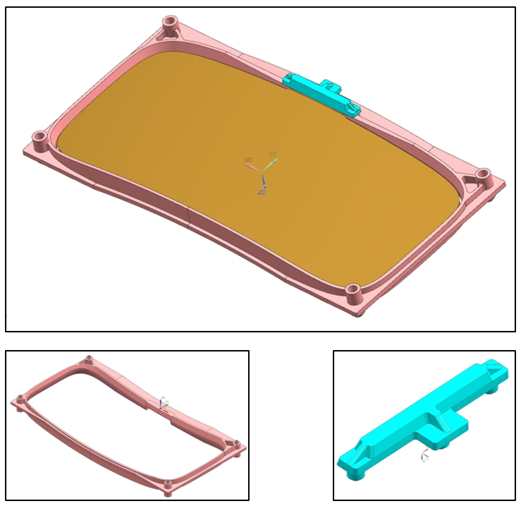
Fig. 1 The jig is divided into two parts: the body (left) and the upper cover (right).
After determining the design of the jig, the ZUSSIN team was going to predict the feasible mold structures including the two-plate or three-plate model. The analysis will involve the runner design and the gate position(Fig. 2). Also using the measurement node to measure the flatness and shrinkage distance (Fig. 3). The main purpose is to obtain high filling efficiency and a flow path scheme with a short cycle and a small amount of deformation.
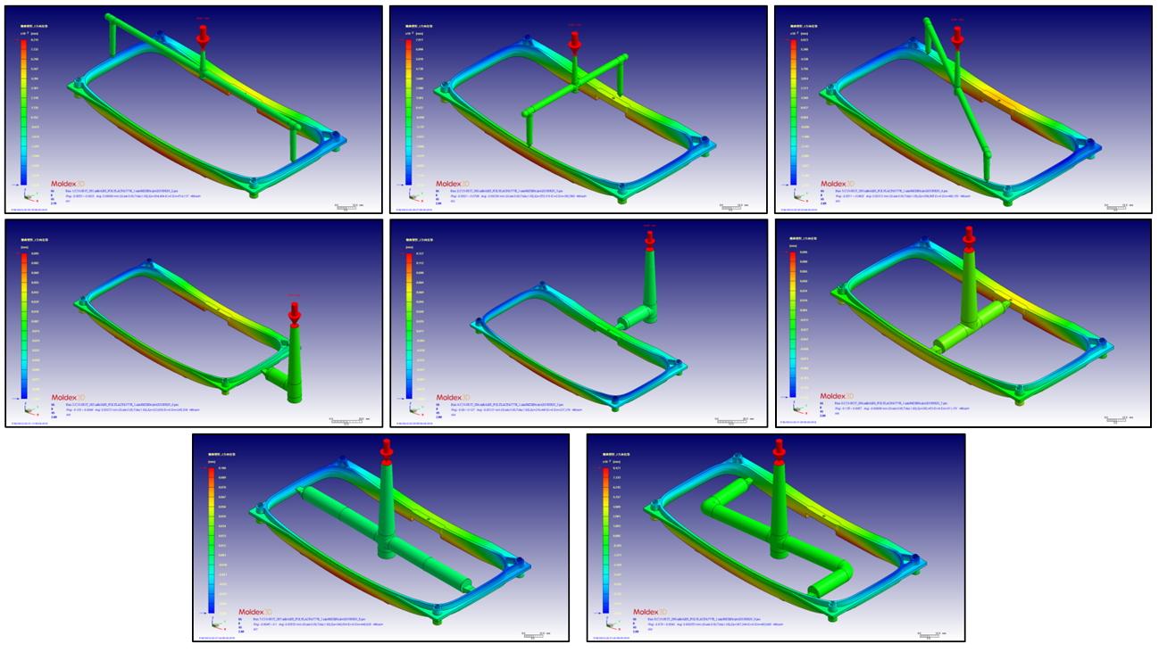
Fig. 2 Different types of runner and gate design
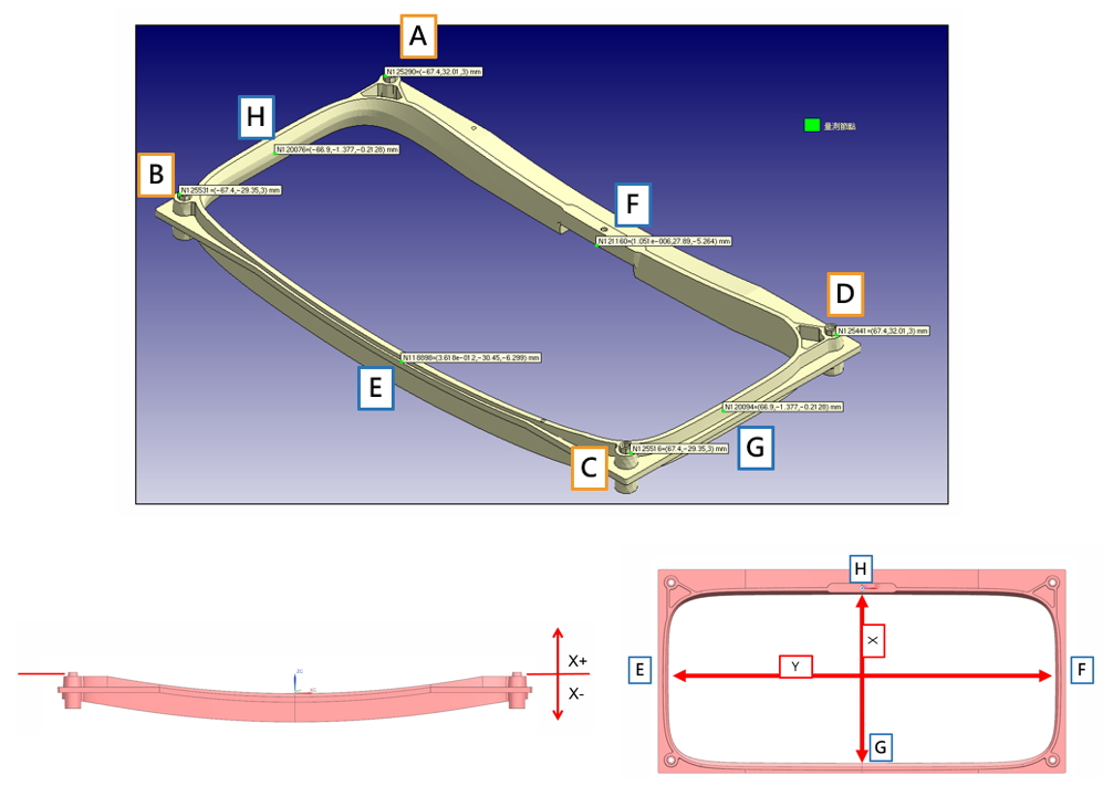
Fig. 3 Using the measurement node to measure the flatness (left) and shrinkage distance (right)
According to the flatness, shrinkage distance results, and considering that the upper and lower cover must be co-molded, the runner design must have enough space for the upper cover. Finally, the runner design shown in Fig. 6 was chosen.
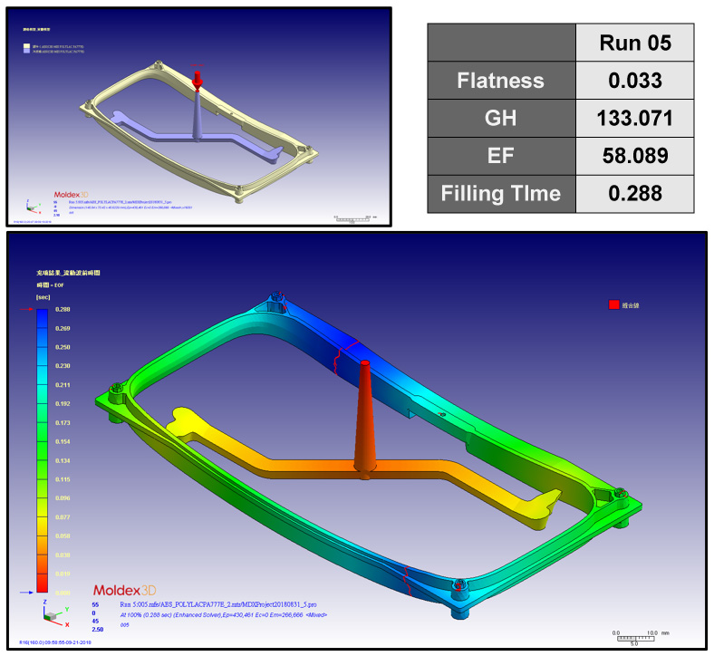
Fig. 4 Final runner design
Next, ZUSSIN’s purpose was to determine the cooling channel design. After running several simulations of cooling channel designs (Fig. 5), they found that the design of the cooling channel did not have much influence on the flatness or the shrinkage distance. Considering the mold structure, they chose Run 16 as the final cooling channel design.
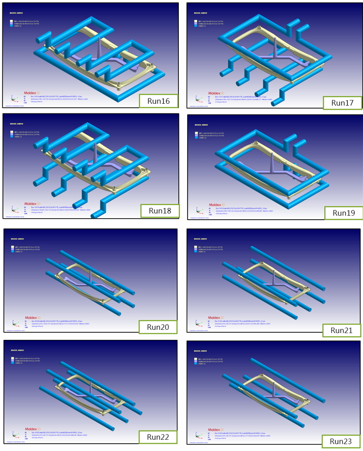
Fig. 5 Different cooling channel designs
The last step was to find the appropriate sub-runner design through Moldex3D so that the upper and lower covers can be co-molded. Since the volumes of the upper cover and the body are very different and the two must be matched, ZUSSIN needed to find the most suitable gate size.
The fit of the jig is to use the three axes and holes located on the upper and lower covers. To ensure the product’s function, the relative hole distances cannot be too different, so ZUSSIN placed the measure nodes on both parts (Fig. 6).
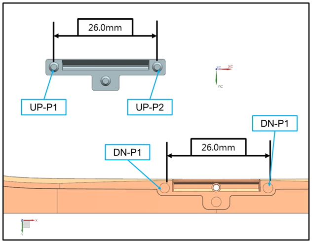
Fig. 6 The measure node locations
ZUSSIN finally chose Run 29 as the final upper cover runner design (Fig. 7). This runner design is thinner than others, and there is more reserved space for the mold. After the trial, they could still adjust the runner design according to the actual situation.
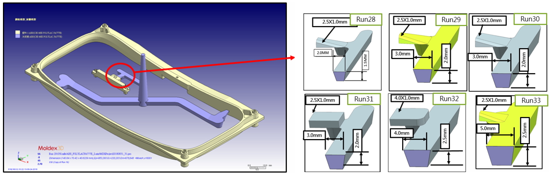
Fig. 7 The upper cover runner designs
Lastly, ZUSSIN conducted an actual mold-trial experiment. When comparing the actual mold-trial results with those of Moldex3D simulation analyses, the simulation results closely reflected the real-life molding scenario and were validated by the mold-trial results (Fig. 8).
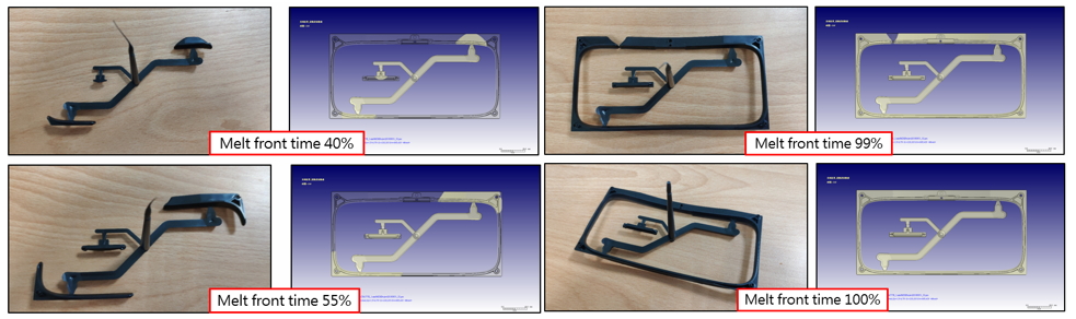
Fig. 8 Actual short shot trial compared to Moldex3D simulation analysis results
Results
With the analysis of Moldex3D, ZUSSIN could quickly and flexibly obtain the information, data, cross-matching, and obtain a better solution for the functional requirements. In addition, they successfully reduced the mistakes of the mold designs and the burden of the production line, and further reduced costs and increased their production capacity. Most importantly, they were able to validate the feasibility of the mold designs from their “rules of thumb”.