

![]()
- Customer: Stanley Black & Decker
- Country: U. S. A.
- Industry: Tools manufacturing
- Solution: Moldex3D Advanced Package; Flow, Pack, Cool, Designer BLM, Fiber, FEA Interface
- View PDF Version
Stanley Black & Decker is a world-leading provider of tools and storage, commercial electronic security, and engineered fastening systems, with unique growth platforms and a track record of sustained profitable growth. (Source: https://www.stanleyblackanddecker.com/)
Summary
Since the fiber orientation will have a significant impact on the component strength, Stanley Black & Decker (Stanley) engineers were tasked with investigating the part strength of a hammer tacker housing made from PA66 with an addition of 30% carbon fibers. However, it is not easy to take into account the effect of fiber orientation on material properties in structural analysis. Stanley engineers leveraged Moldex3D injection molding and Altair structural analysis tools to obtain critical data required to perform accurate structural analysis to ensure overall part strength.
Challenges
- To take into account the effect of fiber orientation on part strength
- To identify stress concentration
Solutions
Stanley Black & Decker engineers used Moldex3D FEA Interface to export the fiber orientation variations along the flow path fields to Altair Multiscale Designer and further mapped the results to Radioss for performing structural analysis.
Benefits
- Observed warpage caused by the anisotropic behavior of fibers
- Identified areas of stress concentration
- Optimized part strength
Case Study
In order to strike the right balance of lightweighting without compromising structural integrity, it is important to take into account the effects of fiber orientations and material properties in structural FEA analysis.
Stanley Black & Decker (Stanley) engineers utilized both Moldex3D and Altair Radioss in order to investigate the part strength of a hammer tacker housing (Fig. 1). The product was made from 30% carbon fiber-filled PA66, and it was expected to pass the 300,000 life test. With the integration of Moldex3D and Altair Radioss, Stanley engineers can gain insight into how the strength of the part would be influenced by the fiber orientation to ensure part strength.
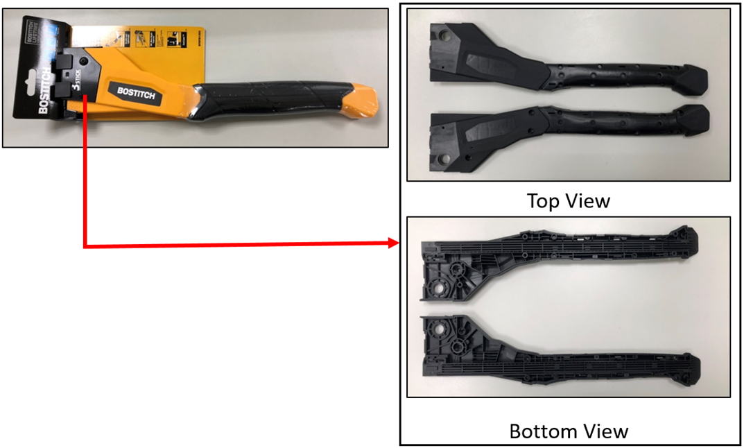
Fig. 1 The hammer tacker housing in this case
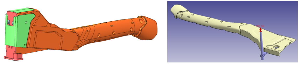
Fig. 2 Part design
Stanley engineers used Moldex3D to obtain injection molding simulation results as well as fiber orientation data. Based on the simulation results, Stanley engineers could evaluate gate locations and make sure that the sprue pressure, air trap, and warpage would meet requirements (Fig. 3). Stanley engineers then used Moldex3D FEA Interface to export fiber-induced anisotropic mechanical properties for further structural analysis.
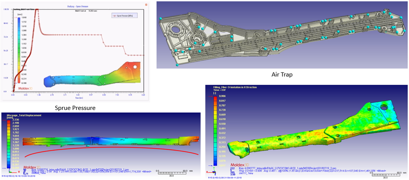
Fig. 3 Sprue pressure, air trap, warpage, and fiber orientation were evaluated in Moldex3D
Then, the engineers conducted a simulation test in Radioss using an isotropic material model. This was performed to test the boundary conditions and the model. After the analysis was done, the mesh was exported for mapping fiber orientation. The Fiber orientation result exported from Moldex3D was mapped to Radioss mesh. Moldex3D mesh was first imported to Radioss, and the fiber orientation result was loaded. Then, Moldex3D mesh was deleted and replaced by Radioss mesh, where the fiber orientation was mapped. The model was output for Multiscale Designer afterward (Fig. 4).
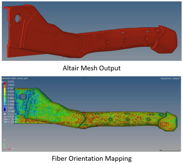
Fig. 4 Moldex3D fiber orientation result is mapped to Radioss mesh.
Stanley engineers set material models and characterization in Multiscale Designer. Unit cell model was defined with discontinuous fiber configuration. Matrix and fiber material property was input, and fiber orientation tensors from Moldex3D were set in the 6-layer laminate set up at three different angles of flow direction (Fig. 5). Non-linear material characterization was also set, and both the material file and fiber orientation file were eventually created for Radioss simulation.
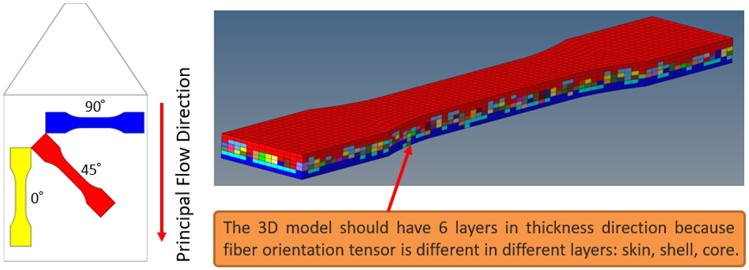
Fig. 5 Laminate set up at three different angles of flow direction
Simulation results without fiber orientation (isotropic material properties) and with fiber orientation (anisotropic material properties) are shown in Figure 6. As shown in Figure 6, the stress and strain results are different since fiber orientation will affect the material properties and lead to different deformation behaviors. In addition, the simulation model considering fiber orientation shows high-stress concentration at specific locations, which would not have been detected without the isotropic material model (Fig. 6).
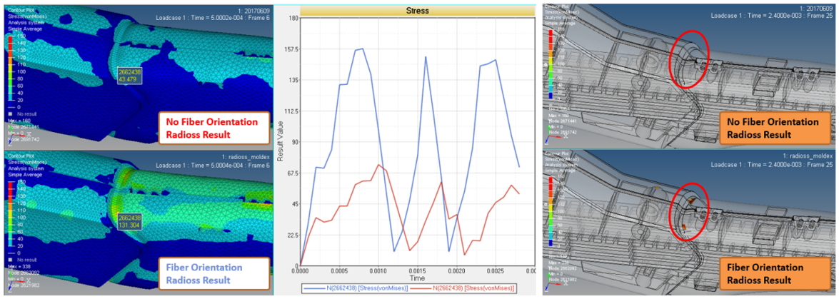
Fig. 6 Unlike anisotropic material property, isotropic one cannot detect high-stress concentration in the model.
Results
Moldex3D helped Stanley Black & Decker take into account the process-induced material properties that would not have been possible before without the integration of injection molding and structural analysis. By integrating Moldex3D and Altair Radioss, Stanley engineers gained deeper insight into how the part would perform in the real world considering the influence of fiber orientation, and increased confidence in optimizing designs to meet light weighting and robustness objectives.