| Pierre Yeh, Senior Engineer at Technical Support Team, Moldex3D |
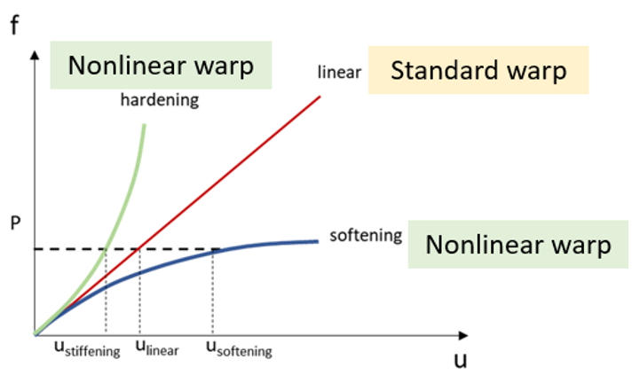
In most structural analysis calculations, in order to quickly obtain the deformation of the structure due to external forces or temperature changes, we use linear structural analysis instead of the iterative method, which is more time-consuming. However, nonlinear structural analysis through the iterative method can consider the influence of displacement on the structure or external force, which cannot be achieved by linear structural analysis. Therefore, it is necessary to obtain nonlinear results.
Moldex3D supports a Nonlinear Warp analysis solver, which provides users with the analysis of finite deformation and geometric nonlinearity (material nonlinearity considerations require other integration features). The figure below describes the differences between nonlinear and linear structural analysis. When there is a thin beam or thin-shell structure in the geometry, and when the deformation is large, it is usually recommended to apply nonlinear warping analysis.
Operating Procedures
Create a project for Warp analysis
Step 1: Create a project in Studio and prepare a model till Final Check. Then the analysis settings are the same as that for Standard/Enhanced Warpage analysis.
Limitation (2022 R1): Non-matching mesh and Shell Mesh are not supported.
Computation Parameter Setting
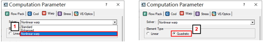
Step 2: In the Warp tab of the Computation Parameter Wizard, select the Nonlinear warp solver. Check Quadratic elements to enable advanced mode, though more computation resource is needed.
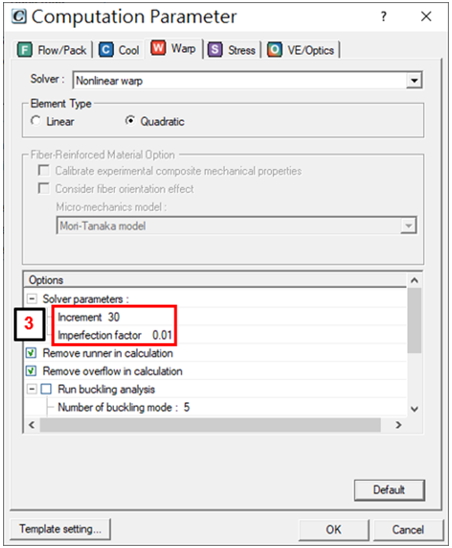
Step 3: Confirm the value of Increment and Imperfection factor (default recommended) in Solver Parameters.
Note: Increasing the Increment value will have better convergence but will increase the analysis time. Imperfection Factor is a coefficient to apply the buckling result in the initial condition of warpage analysis, so Run buckling analysis is also recommended to be enabled.
Step 4: Check Use disk space (scratch directory) as virtual memory for more computation resources in large calculation iterations. The disk location used can be specified in Preference or Install Wizard.
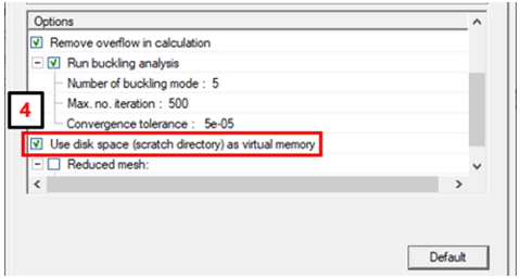
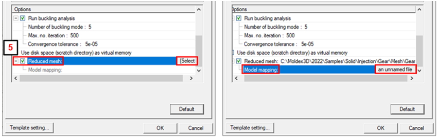
Note: It is recommended to use Reduced mesh for buckling analysis and nonlinear warpage analysis if the computer memory resources (RAM) are not enough. One will need to prepare another mesh model with lower mesh resolution and do mapping with the original model.
Submit for Warpage Analysis
Step 5: Once all analysis settings are done, click Run to submit the job with the analysis sequence of Warp to Computing Manager. After the calculation is finished, one can select the warpage result on the Project Tree and check the deformation prediction.
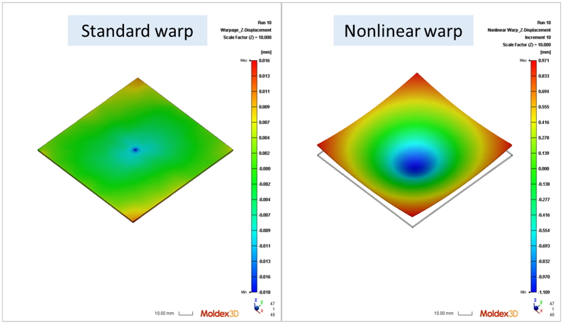
Result: Users can compare the difference between the Standard warp and Nonlinear warp results. In this case, one can see the deformation is significantly larger considering the geometry non-linearity.