
| Joseph Lin, R&D Engineer at Moldex3D |
Warpage prediction is usually a critical issue in injection molding simulations. The linear elastic method is applied in most warpage analysis. In general cases, it is suitable for the model to remain linear, and nonlinear effects from geometry, material, or boundary are not considered. However, the simulation results are sometimes not consistent with the experimental ones, especially for the models with thin geometric characteristics, such as car products and optics components. To compensate for the differences between the numerical simulation and experiment, we tried to introduce the geometrical nonlinear effect into the computation, which will be interpreted as follows.
Nonlinear Structural Analysis
In numerical structural analysis, linear elastic analysis is the simplest way to calculate the deformation of a structure under an external force. However, for real cases from experiments, the nonlinear properties of the geometry or materials can significantly affect the deformation. These effects might lead to a nonlinear relation between force and displacement. Fig. 1 shows the difference in the equilibrium path between the linear elastic and nonlinear elastic analysis.
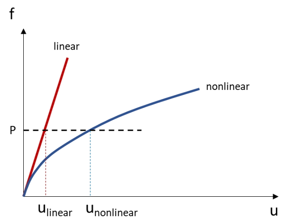
Fig. 1 The difference in the equilibrium path between the linear elastic and nonlinear elastic analysis
In this article, we focus on the nonlinear effect caused by the geometric change. This kind of nonlinearity usually happens in thin, shell-like products or products with significantly uneven thickness distributions. Therefore, to consider the geometrical nonlinear effect, the finite deformation theory must be taken into consideration.
Finite Deformation Theory
The finite deformation theory considers the location changes between the original configuration and the deformed configuration. Therefore, unlike the linear elastic analysis, the stiffness matrix of which remains the same, the structural stiffness and boundary of nonlinear analysis may be altered during the computation due to the change of geometry. Therefore, the structural system can be seen as a function of displacement and can be represented as:
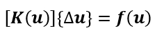
Where  is the structural stiffness,
  is displacement increment, and
  is the external force.
The equation listed above is nonlinear. We need to linearize its tangent stiffness and solve it iteratively. The linearization of the equilibrium system could be written as:
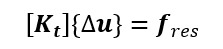
To deal with the iterative calculation, we adopt the Newton-Raphson method, the most renowned way to solve nonlinear mathematical problems. The analysis is considered convergent and finished until the residual force is smaller than the convergence criteria.
Application of Imperfection
Sometimes, nonlinear scenarios do not easily occur in structural analysis during numerical analysis. Whereas the real model is usually imperfect, defects from manufacturing processes might exist in the model. These defects might usually trigger the nonlinear equilibrium path. Which means, for example, most numerical software will apply a tiny perturbation to demonstrate imperfection. Our nonlinear warpage analysis will introduce the eigenvector from buckling analysis also as the imperfection to trigger the nonlinear properties.
“Nonlinear Warpage Analysis” for Warpage Prediction
In Moldex3D, we provide a new solver named “Nonlinear warpage analysis” for users to conduct the warpage analysis. In this new solver, users only need to choose the “Nonlinear warp analysis” from the solver options, and it will automatically consider the nonlinear geometric effect.
Here we first use a simple case to demonstrate the influence of consideration of geometric nonlinearity. As shown in Fig. 2, the results from “Standard warp” and “Nonlinear warp” are compared, and the deformed shape of each result is conspicuously different. Observing the equilibrium path of these results, we can simply find that the geometrically nonlinear property of this model plays a key role during analysis. Therefore, considering the effect of geometric nonlinearity is inevitable for this kind of shell-like product.
Also, the “Nonlinear warp” analysis provides the stress distribution for users to check where the maximum value or stress concentration is.
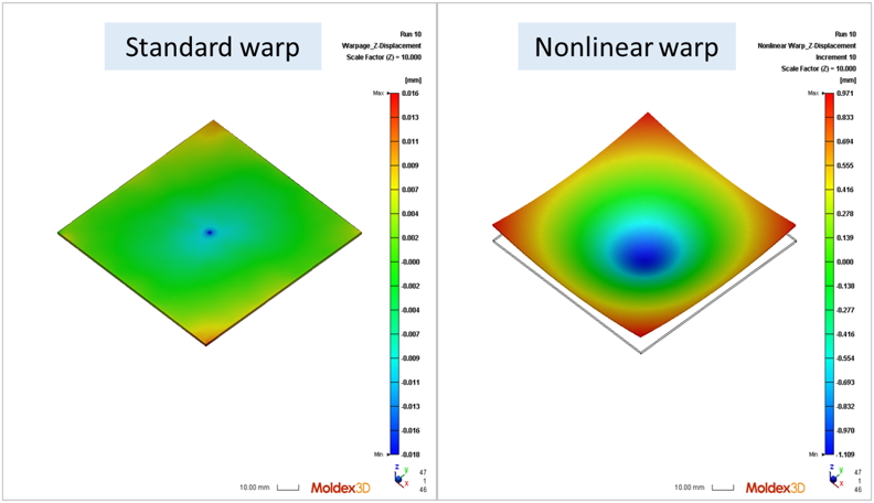
Fig 2. Nonlinear warpage analysis (left), linear warpage analysis (right)
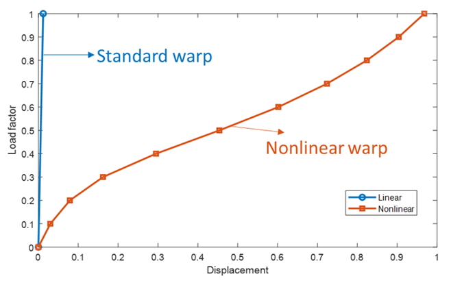
Fig. 3 Load-displacement curve
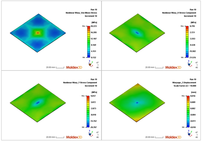
Fig. 4 Stress distribution of each component
Real Case: The Car Part
Car parts are usually constructed with thin thickness for lightweight purposes. As these considerations, the geometric effects might cause not only the geometric nonlinearity but the differential distribution of other physical fields.
Here we select a car part to show the influence of geometric nonlinearity. As shown in Fig. 5, there is an obvious deformation difference between linear and nonlinear warpage analysis. By inspecting the volume shrinkage result near this highlighted area shown in Fig. 6, the value is higher than the ones in other regions due to the thinner thickness value. From this case, the differential shrinkage distribution, which might come from the model geometry, process conditions, or fiber existence, influences the deformation largely when considering the geometric nonlinearity. Therefore, for shell-like products, we usually suggest users select “Nonlinear warp” analysis for deformation prediction.
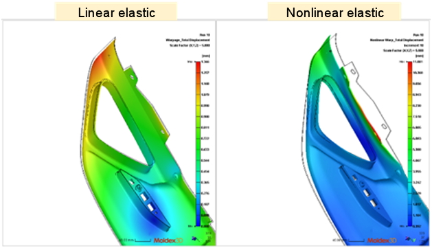
Fig. 5 Comparison of linear(left) and nonlinear results(right)
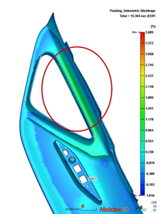
Fig. 6 Volume shrinkage from Filling/Packing stages
Application of the Reduced Mesh
Due to the iterative process, it is well-known that the nonlinear analysis is quite time-consuming and has a high computation cost. Also, the mesh for flow analysis is not appropriate for structural analysis because of its large element numbers and elemental shape. For example, from Fig. 7, the left mesh is constructed originally for the flow analysis, but the mesh of the boundary layers is sometimes not very suitable for structural analysis because the elements might be distorted under loadings. Thus, we usually suggest users construct the mesh which is like the right one shown in Fig. 7 which has uniform element distribution.
Here, Moldex3D provides an interface that allows users to import the mesh whose element number and quality are more suitable for structural analysis. This operation can significantly decrease the computational cost and keep the important physical values by using our mapping tools for data from injection simulation.
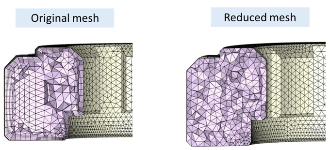
Fig. 7 Comparison of the original mesh and reduced mesh
Conclusion
Except for standard and enhanced warpage analysis, Moldex3D provides another warpage solver, which considers the geometric nonlinearity. We strongly recommend that users choose this solver for warpage analysis for shell-like products, car parts, and optics components. Moreover, we also provide an interface for users to use the models with fewer element numbers to conduct this analysis. With this operation, the total computational cost for the analysis will be lower.