
Barton Lin, Principal Engineer of CoreTech System (Moldex3D)
Resin Transfer Molding (RTM) is currently one of the most cutting-edge emerging technologies, widely used in the production of electronic devices, automobiles, shipbuilding, aerospace, and wind power generation products. However, the RTM industry still faces some challenges. For instance, the fiber placement in the product significantly affects mold flow behavior, incorrect fiber orientation can lead to resin flow behavior that is not easy to predict accurately. Therefore, precise fiber orientation settings are very important for RTM simulation results.
Moldex3D recently released Studio 2023, which offers three methods of fine-tuning RTM fiber orientation according to user s ‘ needs, to obtain more accurate flow analysis results. These three methods include: (1) manual customization: set orientation using R1/R2, (2) import .ls files, and (3) import .inp files (CSS8 format). Users cannot only manually adjust fiber orientation, but import fiber orientation data obtained from Dyna and Abaqus (in .ls and .inp (CSS8) formats) into the existing mesh for a more accurate fiber orientation. The workflow involves the following step.
Getting Started: Create a run for RTM simulation
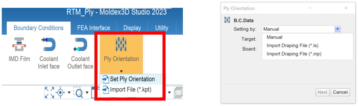
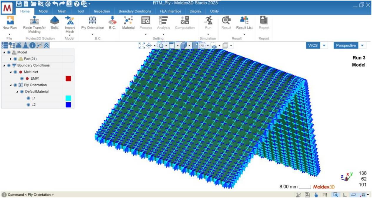
Create a new run in Studio with Molding Process of Resin Transfer Molding and import the RTM model. Once there is a MFE for RTM in the run, the ply orientation can be set by selecting “Set Ply Orientation” from the boundary condition drop-down menu in the Ply Orientation column. The setting page will open, and the three methods described above can be selected from the Setting By menu for configuration.
Method 1: Manual – Set orientation using R1/R2
The manual customization feature allows users to customize fiber orientation parameters, such as the reference surface and fiber arrangement angle, according to their understanding of the orientation. The steps for manual ply orientation setup are as below:
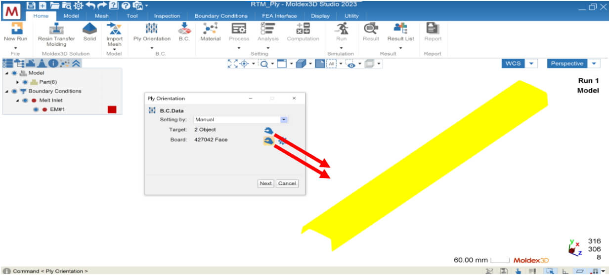
- Select Manual from the Setting by drop-down menu
- Target : choose the target Ply for orientation setup
- Board: select the surface of the Ply
- Press Next to proceed to the next step
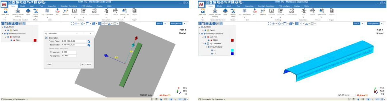
- Project Plane: There will be a default value, and you can modify the normal vector of the projection plane.
- Base Vector: Input a vector that represents 0 degrees on the plane (displayed as a red arrow).
- Specify the angles of R1/R2 relative to the Base Vector.
- Press OK to complete the orientation setting.
Method 2: Import LS file
This method is applicable when the user obtains the fiber draping information in the mold from LS-DYNA as an .ls file, and then imports it into Moldex3D for fine-tuning. The setup steps are as below:
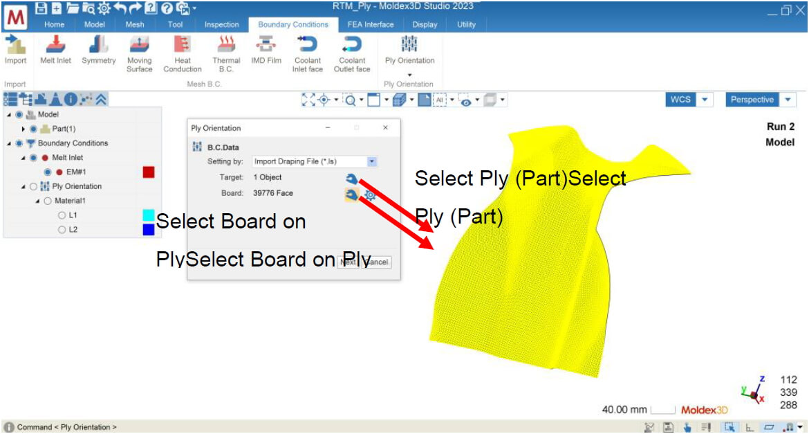
- Select Import Draping File (*.ls) from the Setting By menu.
- Target: Select the ply for orientation setup.
- Board: Select a surface on the ply.
- Press Next to proceed.
- Select the corresponding ls file for the Draping File
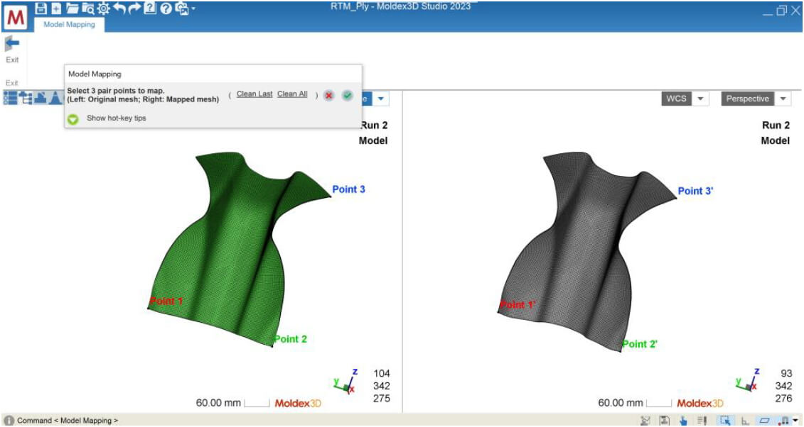
- Press the View/Edit button to perform Mapping
- The .ls file will be displayed as an object with no attribute and three methods will be provided for mapping the project model with the ls file:
i. Original: Use the original position of the .ls file.
ii. Auto Move: Automatically move to a better position.
iii. 3-points mapping: Select three points each for the project model and the .ls file to perform mapping. - After mapping is complete, press OK to finish setting the ply orientation.
Method 3: Import INP file (CSS8 format)
This method is applicable when the user obtains fiber draping information *.inp file (CSS8 format required) from Abaqus and imports it into Moldex3D for fine-tuning using this feature. The setup steps are as follows:
- Select Import Draping File (*.inp) from the “Setting by” menu.
- Target: select the ply(s) for setting the fiber orientation, all plies corresponding to the INP file must be selected together.
- Press Next to proceed to the next step.
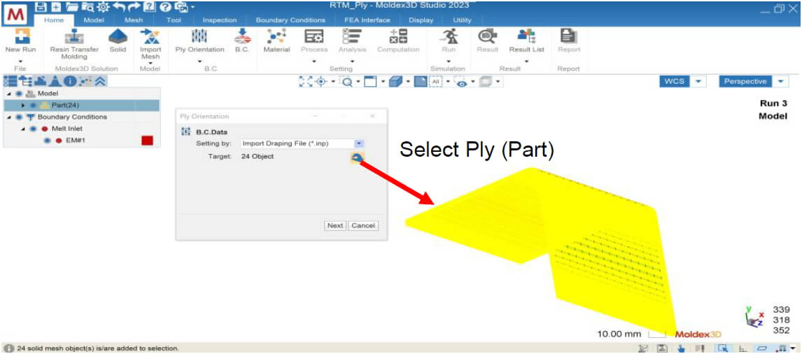
- Select the corresponding INP file for Draping File (the inp file needs to be CSS8 format)
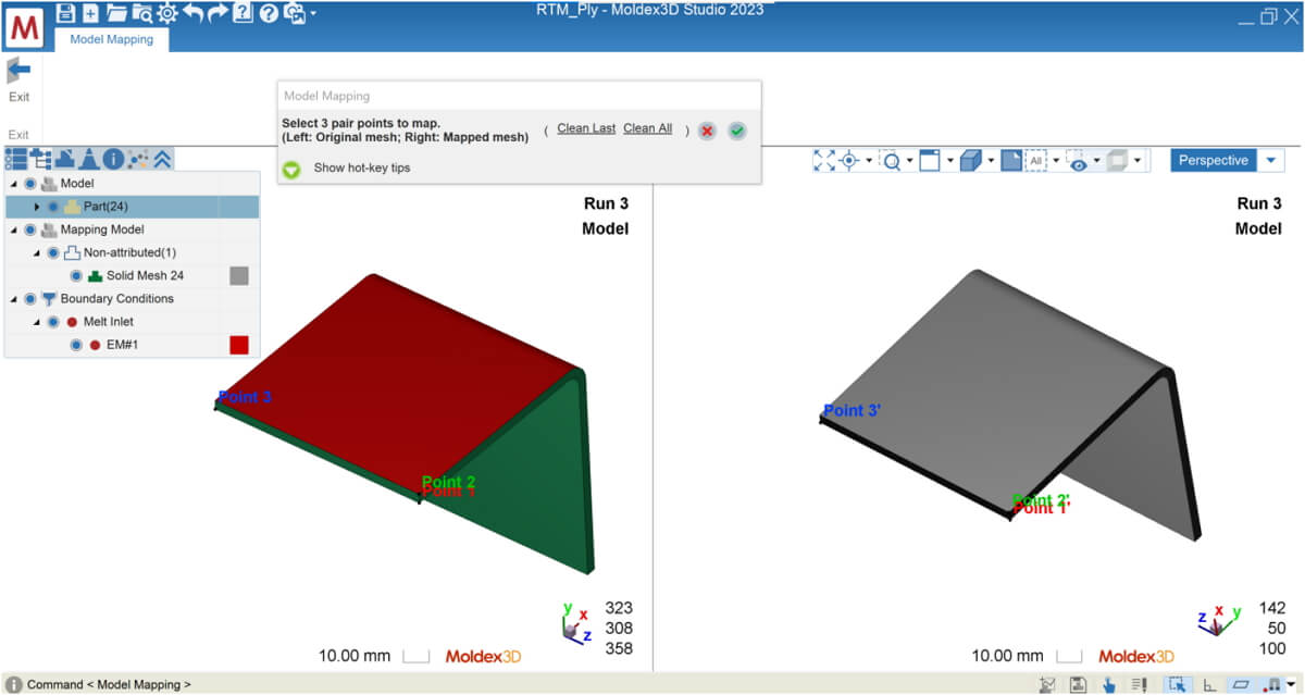
- Press the View/Edit button for alignment (Mapping)
- The INP file will also be displayed as an object with no attributes and provides three ways to align the project model with the INP file:
i. Original: Use the original position of the .ls file
ii. Auto Move: Automatically move to a better position
iii. 3-points mapping: Select three points each for the project model and the .ls file to align - After mapping is completed, press OK to finish the draping setting.
Perform RTM Simulation: Proceed to Analysis and Result Interpretation
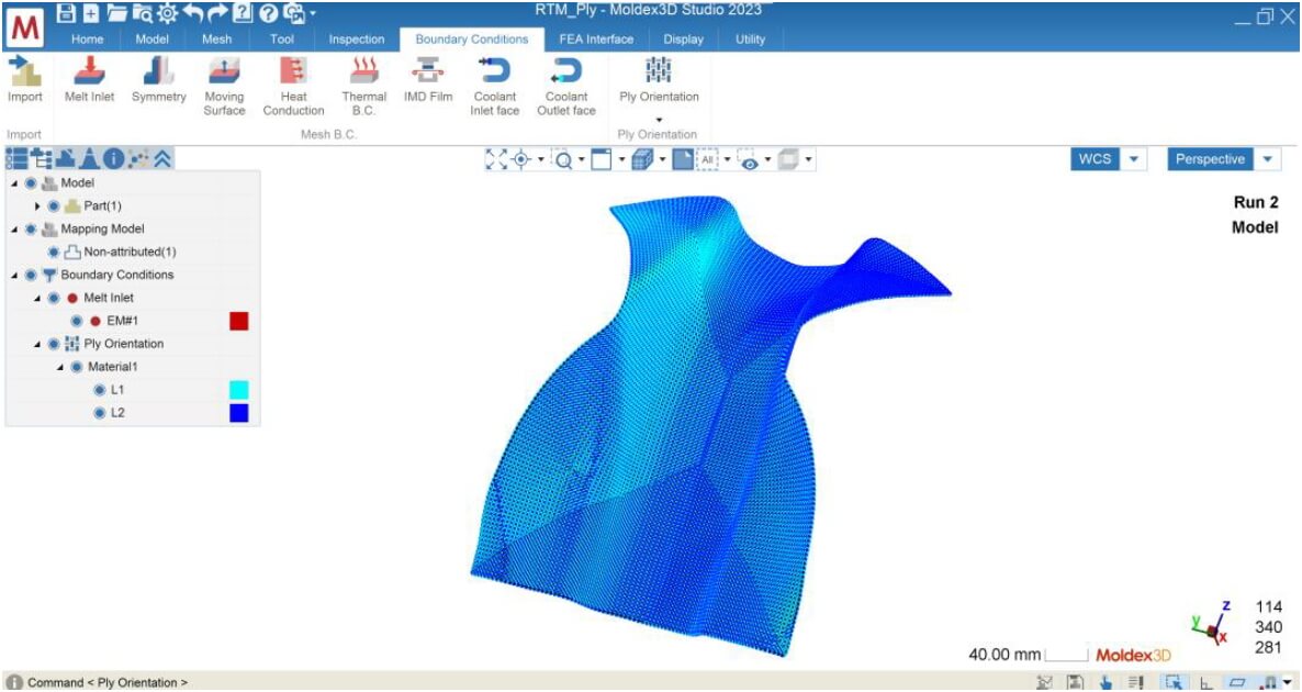
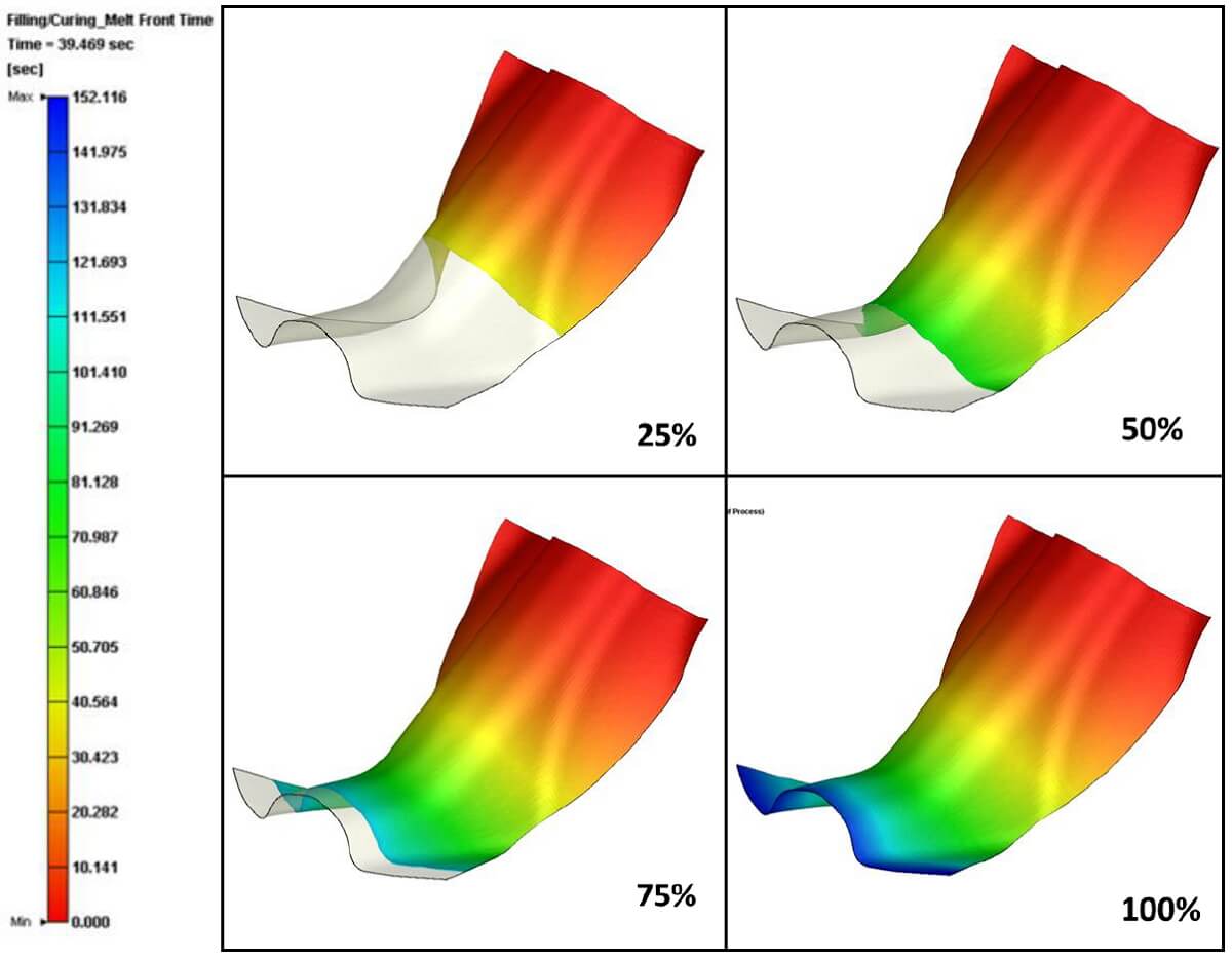
Finish material selection, RTM process condition, and other analysis settings, so the run is ready to submit for calculation. The case below shows the Melt Front Time result with Method 2 after Filling analysis. The Ply setting then will affect resin transferring phenomena and other product quality, such as mechanical property.
Summary
Moldex3D Studio 2023 offers RTM simulation which gives users the ability to modify fiber orientation through manual customization, inputting *.ls files, or inputting *.inp files, depending on their needs. Accurate fiber orientation is crucial for accurately predicting the resin flow behavior in RTM processes, so utilizing this new added feature can greatly aid in the RTM mold filling results.