- Customer: Taiwan University of Science and Technology
- Region: Taiwan
- Industry: Education
- Solution: Moldex3D Advanced / Injection Compression / Optics / Viscoelasticity
- View PDF Version
Executive Summary
The market demand for high-precision injection molding of optical parts is rising. However, due to the strict optical requirements, it is important to avoid residual stress, warpage, and sink marks issues. The Precision Manufacturing Lab (PML) at TUST aims to develop an In-Mold Micro Compression (IMMC) process to address the above optical challenges and optimize the injection molding process. They used Moldex3D injection compression solution to simulate and evaluate the impact and the effectiveness of IMMC process. According to the simulation results, IMMC process could significantly reduce sink marks and volume shrinkage, and increase light collection efficiency. This case also demonstrates that Moldex3D can provide excellent correlation between simulation results and real-life molded parts.
Challenges
- Uneven pressure distribution
- High shrinkage rate
- Warpage
Solutions
Use Moldex3D Injection Compression simulation solution to estimate and verify the effectiveness of IMMC process.
Benefits
- Obtain uniform pressure distribution
- Enhance luminance by 7.35%
- Reduce volumetric shrinkage rate from 6.62% to 4.25%
Case Study
 Fig. 1 A prism array is a plastic optical part designed to collect sunlight
In this case, the PML lab tried to investigate the possibility of using In-Mold Micro Compression process to improve the performance of plastic prism arrays. A prism array is a plastic optical part designed to collect sunlight. Due to its structure, the gate location was placed on the thin-wall region, which resulted in flow imbalance and higher volumetric shrinkage, causing problems in light collection, transmission and light output. In order to reduce the residual stress and volumetric shrinkage, the PML lab decided to use Moldex3D molding simulation software to help determine the optimal molding process.
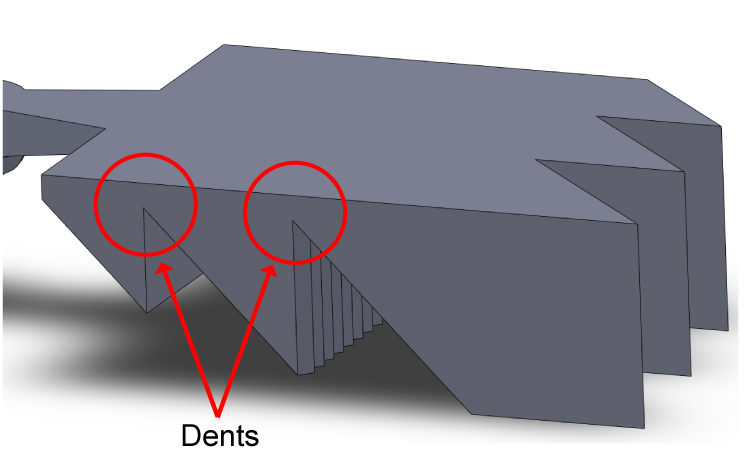 Fig. 2 The optical part has two dents which resulted in flow imbalance
First of all, the PML lab utilized Moldex3D to simulate the traditional injection molding process. The analysis result shows that the sink mark index is higher in thicker sections (Fig. 3-left). Since the melt temperature is high, the surface is pulled inward, causing sink marks. The sink mark simulation result also indicates that higher potential shrinkage will occur on the end of the part (Fig. 3).
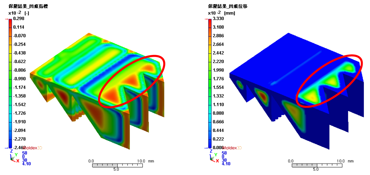 Fig. 3 The sink mark index (left) and sink mark displacement (right) in packing stage
After simulating the injection molding process, the lab used Moldex3D to test the idea of using the new process, IMMC, to optimize the part. Based on the simulation analysis result, the maximum volumetric shrinkage of IMMC (Fig. 4) has been decreased by 18.9% comparing to the injection molded one (Fig. 4). As for the warpage problem, IMMC also improves the Z displacement by 71% (Fig. 5).
(a)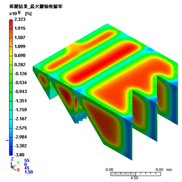 (b)
(b)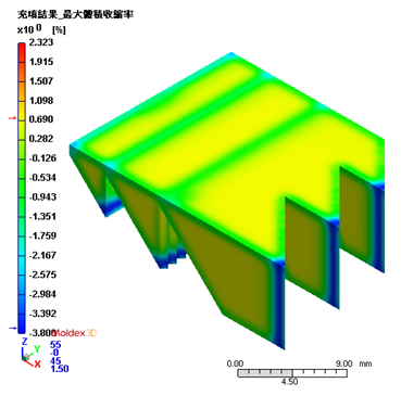
Fig. 4 The packing analysis shows the maximum volumetric shrinkage of (a) the injection molded part is between -2.9%~2.323% ; (b) the IMMC part is between -3.7%~0.69%
(a)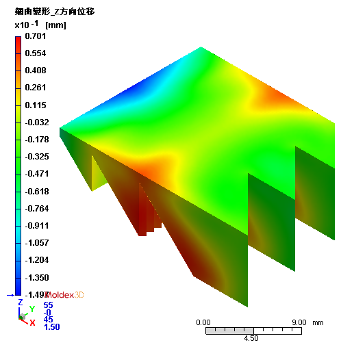 (b)
(b)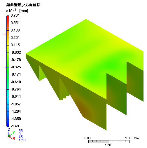
Fig. 5 The warpage analysis indicates the Z displacement of (a) the injection molded part is between -1.497~0.701mm (b) the IMMC part is between -0.325~0.311mm
Comparing the total fringed pattern analysis (Fig. 6) between the two different molding processes using Moldex3D, more obvious fringed patterns were found near the gate of the injection molded one. The analysis shows the injection molded optical part has large residual stress induced by higher packing pressure. The IMMC part, however, has less obvious fringed patterns near the gate due to that the in-mold compression can help lower pressure near the gate.
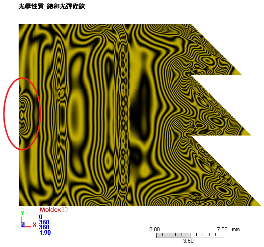
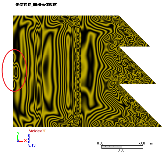
Fig. 6 The total fringed pattern analysis results between the injection molding process (left)
and the IMMC process (right)
The PML lab then conducted a correlation study of predicted simulation results with actual molded parts to validate the use of the simulation analysis. The sink mark analysis result predicted there would be sink marks occur, and the predicted performance matches the experimental result perfectly (Fig. 7). The IMMC simulation result was also validated with the experimental result. Fig. 8 shows that IMMC process can successfully eliminate sink marks and produce optical part without defects.
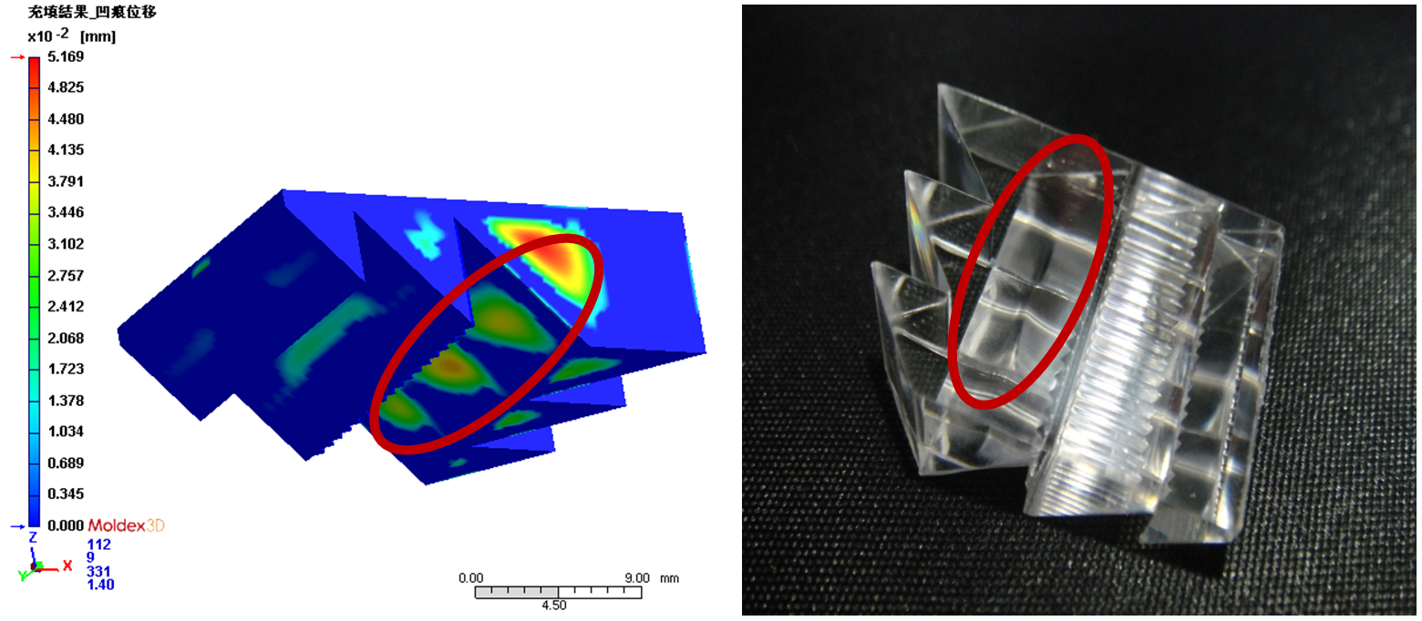 Fig. 7 Moldex3D’s sink mark analysis result matches the actual molding result
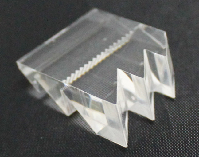 Fig. 8 The part produced by IMMC process has no significant defects
Conclusions
The lab used LED light to further validate the part. The average luminance of the part from IMMC and injection molding process are 299Lux and 321Lux. The illumination has been enhanced by 7.35%.
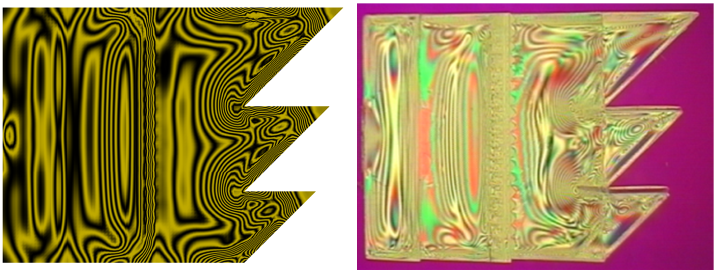
Lastly, the lab validated the fringed pattern result of the two processes. Fig. 9 demonstrates an excellent correlation between the simulation analysis result of the fringed pattern and the actual mold trial result.
The simulation results matched well with the results of the real experiments, which demonstrates that the Moldex3D simulation solution can effectively simulate and optimize the molding process of optical components. In addition, using Moldex3D simulation solution can reduce the cost and risks associated with testing real mold trials.

