  |
Victor Sun, Deputy Technical Manager at the R&D Division, CoreTech System (Moldex3D) Young Huang, UX Designer at the R&D Division, CoreTech System (Moldex3D) |
With the 3C product development toward lightweight and multi-functionality, the technology of IC Packaging process is also getting smaller and more exquisite. Facing the demands of service life and reliability, it is critical to find an optimized configuration for IC packaging to reduce the risk of defect occurrence and achieve the best product protection. Since the factors that affect encapsulation quality increases with the process complexity, it will be more difficult to find an optimal solution at the R&D stage. Moreover, the IC packaging materials and relevant components are all very expensive, so it is necessary to utilize CAE analysis instead of trials and errors at the development stage and find the optimal solution. Thus, the material and delivery costs can be greatly reduced.
The IC Packaging Solutions in Moldex3D Studio covering transfer molding, molded underfill, capillary underfill, potting and compression molding can simulate the filling process of encapsulation. Also, the features including Venting analysis, Wire Sweep analysis, Paddle Shift analysis and Post Mold Curing analysis can be helpful for a more realistic simulation. The IC packaging simulation workflow in Studio is introduced as follows.
1. Modeling
Select “Encapsulation” in the Molding Type tab (Fig. 1). Then, import a completed mesh or prepare a model using the tools in Studio. Using the Encapsulation Component wizard, users can generate IC items from 2D curves, and specify the positions and thickness. Therefore, the Hybrid mesh will be automatically generated during the mesh generation (Fig. 2). Please note that different modules should have corresponding attributes of component and inlet types. For instance, there should be a Compression Zone and Moving Surface BC in the compression molding analysis; the Feed Pass should be set on the Overflow in the Potting analysis.
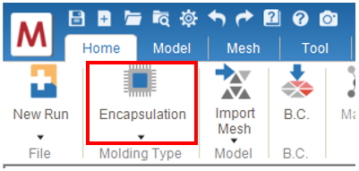
Fig. 1 Select “Encapsulation” in the Molding Type tab.
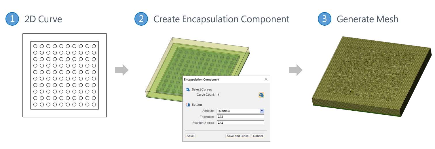
Fig. 2 Create encapsulation components and generate the Hybrid mesh.
2. Boundary Condition Settings
Based on the process types, the Boundary Condition tab provides different boundary conditions for setting (Fig. 3). The Dotting and Potting Pass can be set for Capillary Underfill and Potting analysis (Fig. 4); The Charges be assigned Compression Molding analysis; Fixed Constraint boundary conditions can be added for analysis such of Paddle Shift (Fig. 5).
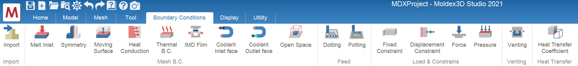
Fig. 3 The Boundary Condition tab
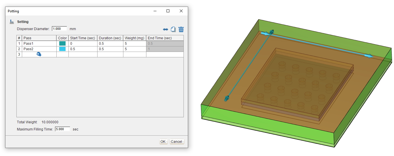
Fig. 4 Potting Pass setting
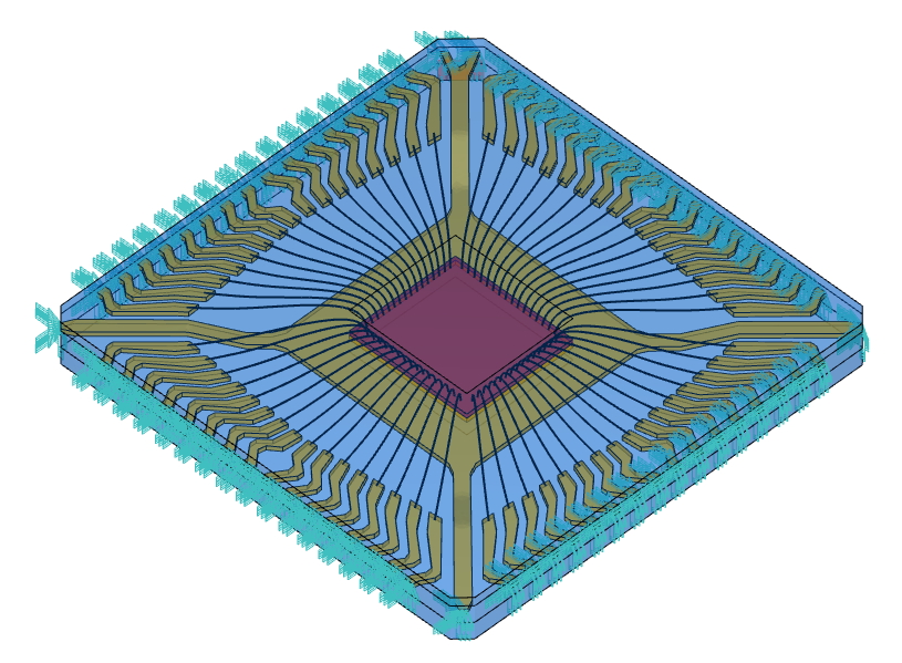
Fig. 5 Fixed boundary condition setting for the paddle
3. Material Settings
Specify the materials for different components and properties from the Moldex3D Material Bank (Fig. 6). Users can also customize the materials according to their requirements.
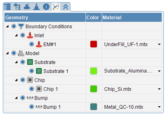
Fig. 6 Set the materials based on the item properties.
4. Process Condition Settings
If the Inlet BC is set on the epoxy, one can select the Transfer Molding, Molded Underfill or Capillary Underfill modules as the analysis type (Fig. 7). If the mesh contains the Compression Zone, we can select Compression Molding, Embedded Wafer Level Packaging or No-flow Underfill as the analysis type. If the Dispensing/Dotting/Potting BC has been set, the analysis type will be automatically selected and locked. For the processes that should consider surface tension (e.g., Capillary Underfill process) according to the flow behaviors, users can proceed the contact angle settings in the Advanced Setting (Fig. 8).
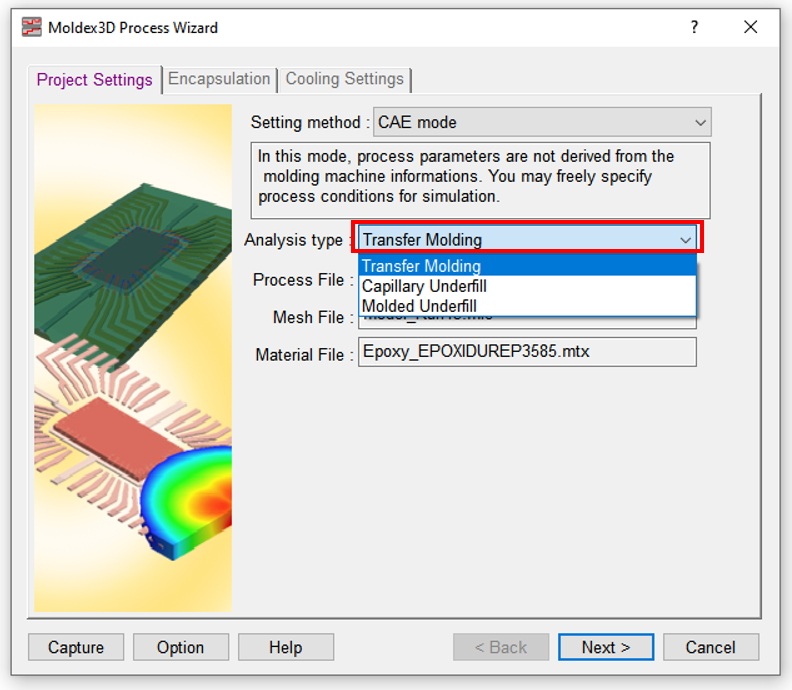
Fig. 7 Select the analysis type.
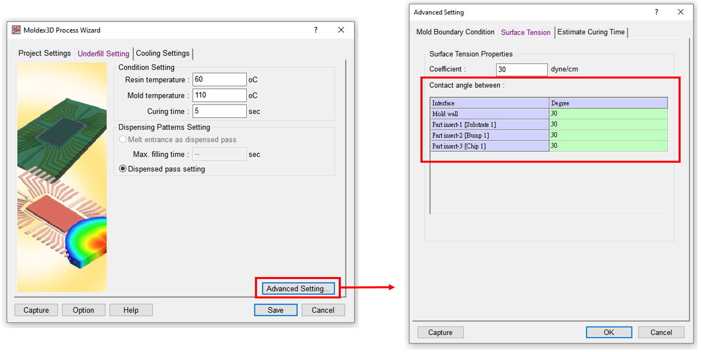
Fig. 8 Contact angle settings in the Advanced Setting
5. Analysis Sequence
Set analysis sequences including Filling, Curing and Warp (Fig. 9). Also, Paddle Shift and Wire Sweep can be added after Filling sequence to enable the corresponding analysis with one-way FSI (fluid-structure interaction) consideration. If Filling – Two-way Paddle Shift (F/PS) added to replace F+PS, it will enable two-way FSI, and the Paddle Shift output will be generated together with the Filling results.
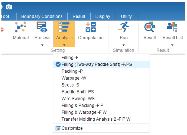
Fig. 9 Analysis sequence settings
6. Analysis Settings
In the Encapsulation tab, users can select the required Stress Solver and calculation model for wire sweep and paddle shift analyses. If the F/PS, Filling – Two-way Paddle Shift, has been specified, we can set the data exchange step of the two-way FSI at this step (Fig. 10).
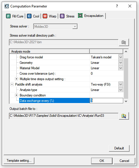
Fig. 10 Select the analysis model and specify the data exchange step of the two-way FSI in the Encapsulation tab
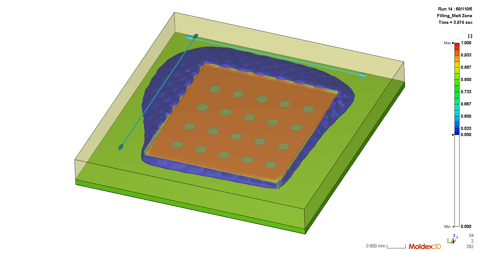
The encapsulation simulation results in Studio visualize the flow behaviors, air trap positions (Fig. 11), wire sweep (Fig. 12), the trend of paddle shift (Fig. 13), capillary flow behaviors of underfill (Fig. 14) in the filling/compression process of the melt. Based on the results, users can modify the IC design or process parameters to prevent defects such as Air Trap, wire overlap and excessive paddle shift. Without the experimental trial-and-errors, the IC packaging design quality can be more efficiently enhanced.
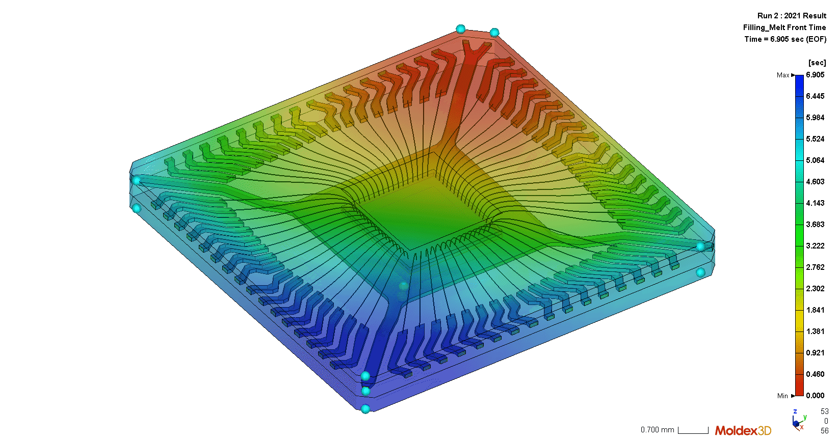
Fig. 11 The flow behaviors and air trap positions can be visualized.
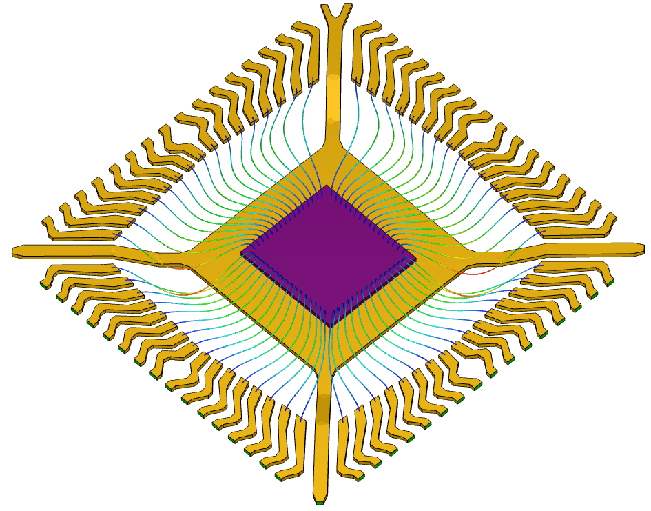
Fig. 12 The wire deformation trend can be shown through the features of Wire Sweep and deformation analysis
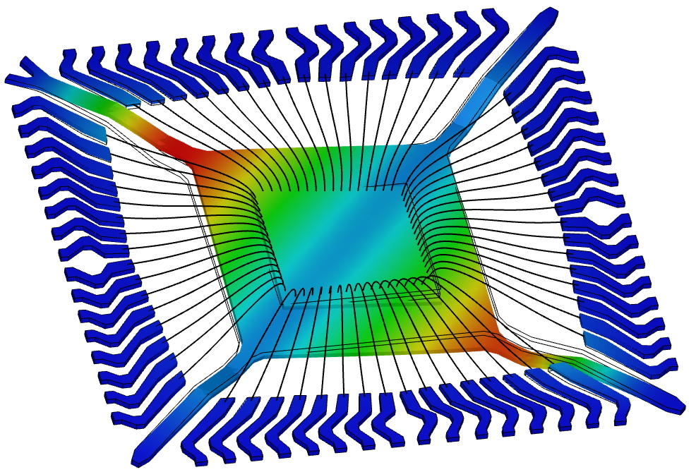
Fig. 13 Paddle shift – total deformation results