Resin Transfer Molding (RTM) is one of the manufacturing methods used to produce Fiber-reinforced plastics (FRP) products. These have been widely used in aircraft and automotive parts because of their high-strength and durable-stiffness material properties. In RTM process, the dry fiber mat is placed in the cavity first, and the thermoset resin is then injected into the cavity.
The biggest challenge in RTM process is to select the appropriate inlet and venting locations in order to avoid flow imbalance. Since the values of anisotropic permeability in the fiber mat and the fluid viscosity both increase over time, it’s difficult to predict the complicated filling behavior of the resin without a 3D simulation tool. Therefore, users can utilize Moldex3D Resin Transfer Molding (RTM) to visualize the filling behavior in order to optimize the process and make mold design modifications before production.
Moldex3D’s Resin Transfer Molding (RTM) is a 3D CAE module for simulating Resin Transfer Molding process. The RTM module has a smart and user-friendly wizard to help users assign RTM parameters and is able to provide accurate filling/curing analysis results. The following steps help users to properly set the process conditions for Resin Transfer Molding simulations.
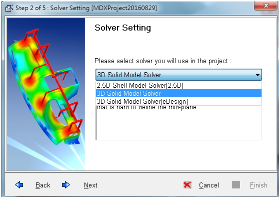
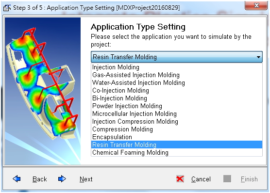
Step 1: Create a new project, select the 3D Solid Model Solver, and choose the Resin Transfer Molding module.
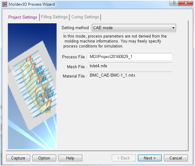
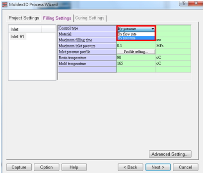
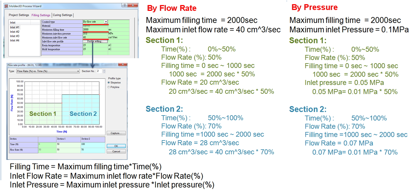
Step 2 Filling Settings: In the Process Wizard, the filling process of Injection Molding module is controlled by the filling time, while the RTM filling process is controlled by the flow rate and the pressure. There are two types of filling settings for a RTM analysis: By Flow Rate and By Pressure.
- By Flow Rate:Use Maximum inlet flow rate and assign the flow rate profile in Profile setting.
- By Pressure: Use Maximum injection pressure and assign the pressure profile in Profile setting.
Also, users can set Maximum filling time for a termination timing of filling analysis, and set Resin temperature and Mold temperature to control the temperature distribution during the filling process.
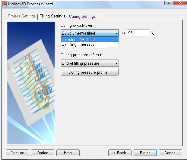
Step 3 Curing Settings: In this tab, users can specify the curing switch timing and the pressure.
Users can specify another curing switch timing through By volume(%) filled, and the curing switch-over will occur as the cavity is filled with a user-defined percentage. Otherwise, when By filling time(sec) is selected, the curing switch-over will occur at the user-defined time.
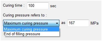
On the other hand, the curing pressure is controlled by the reference pressure and the pressure profile and the curing analysis will end at the given Curing time. Select reference curing pressure between End of filling pressure and Maximum curing pressure, and assign the pressure variation profile by clicking the Curing pressure profile.
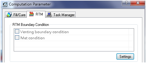
Step 4: Prior to running a RTM analysis, Venting boundary condition has to be set. Launch Designer workspace to set the RTM boundary condition, click Setting under the RTM tab in Computation Parameter, and users can then define the venting condition.
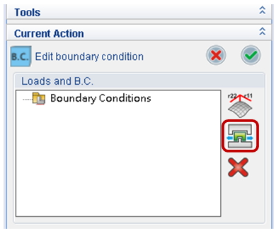
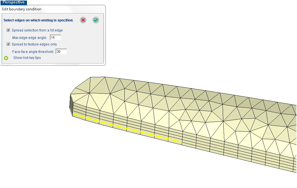
Step 5:In the workspace, click Add venting BC and select the location of the venting BC. The faces near the venting selected location will be defined as venting BC. Click ![]() when it is done. After finishing the process, venting BC, and other project settings, users can then launch the filling and curing analysis.
when it is done. After finishing the process, venting BC, and other project settings, users can then launch the filling and curing analysis.
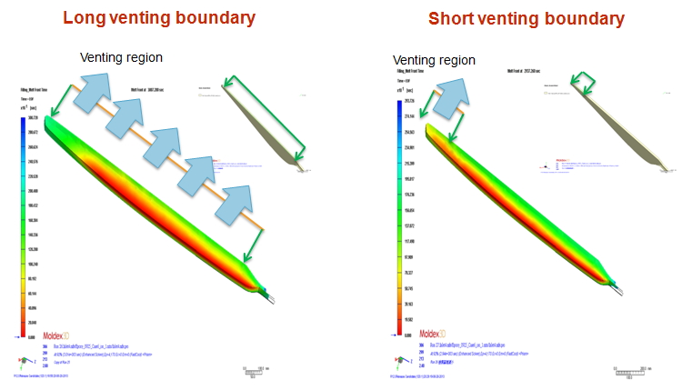
Filling patterns with different lengths of venting boundary
Venting is an important factor in RTM process. In the filling stage, the resin flows from the inlet to the venting boundary. Different lengths of the venting boundary condition will result in different flow behaviors as shown below.
