
Multi-Component MoldingMulti-Component Molding (MCM) has been popularly used for producing complex parts in a variety of industries, including electronics, consumer products, and automotive. This technology offers an innovative approach to combine several components inside the mold by eliminating the need for post-molding assembly, bonding, or welding as well as reducing the overall manufacturing cost. This process also promotes design flexibility and improves part aesthetics, value, quality, and functions. The first component known as part insert, is pre-placed in the cavity to be subsequently over-molded by the polymer melt. In general, part insert can be made of either a pre-molded plastic or metal. Therefore, it is commonly known as either over-molding or insert molding, respectively. To prepare a good mesh model that incorporates part insert can be challenging when accurate analysis results are aimed to be attained at the same time.
Moldex3D Multi-Component Molding (MCM) provides a powerful simulation tool for both over-molding and insert molding as well as a robust pre-processor to automatically generate surface and solid meshes of the part, part insert and mold base. In the previous version, Moldex3D R14.0 supports non-matching mesh topology at the contact faces between part and part insert through which the analysis could have continuous results across the non-matching mesh boundary. As a result, users could save lots of time and effort in completing the mesh preparation without bothering matching the mesh elements. Moldex3D R15.0 further extends the functionality of this non-matching feature by allowing users to generate a solid mold base for the model with non-matching part and part insert (Fig. 1). Thus, it provides two other benefits besides faster mesh preparation: more accurate results for cases that are typically dependent on fine solid mold base mesh resolution and faster solver calculation by which solver does not need to auto-partition the mold base mesh.
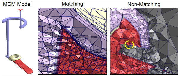 Fig. 1 Moldex3D R15.0 supports both matching and non-matching mesh models;
solid mold base can be generated in non-matching model.
Following is a case study of generating a solid mold base using non-matching feature for an over-molding model.. Both part and part insert materials were PC+ABS, and the melt temperature, mold temperature, and initial part insert temperature were 265 °C, 75 °C, and 30 °C, respectively. The results from matching mesh model were used as the reference for the non-matching mesh model. The temperature profile and the Z-displacement were evaluated. The simulation result of the non-matching mesh model is similar to the result from the matching mesh model (Fig. 2 and 3). This indicates that solid mold base in non-matching mesh model can work well.
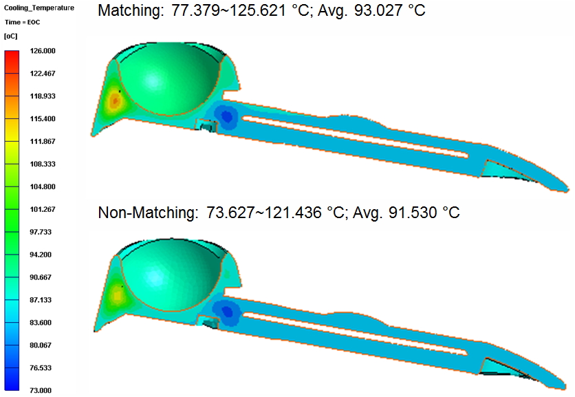 Fig. 2 Comparing temperature results between Matching mesh and Non-matching mesh models.
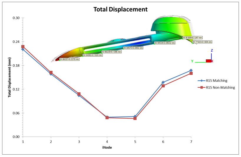 Fig. 3 Matching and non-matching mesh models yield close Z-displacement results.
Moldex3D offers more advanced non-matching mesh technology. It promotes easier and faster mesh preparation with its available non-matching feature and allows users to generate a solid mold base for this non-matching mesh model that can lead to more accurate results and faster calculation from a solver’s point of view at the same time. Hence, this innovative technology can further enhance the benefits of typical MCM analysis.