
Moldex3D Gate Location Advisor can increase the feasibility of mold manufacturing. In the injection molding process, the quality of the product is closely related to the mold design. Particularly, the location and number of gates are important parameters in the mold design. Therefore, the influence of gate design on product quality is extremely important. Inadequate gate design may cause defects such as poor appearance, poor quality of weld line, high shear stress and warpage. In addition, this function provides an advanced flow length ratio (Flow length from gate to end/Average wall thickness) tool, assisting users in evaluating their design. At this time, the Moldex3D 2023 further enhances the Gate Location Advisor for a better gate design and can quickly provide preliminary design recommendations to make flow balance distribution more reasonable.
Step 1. Import Geometry
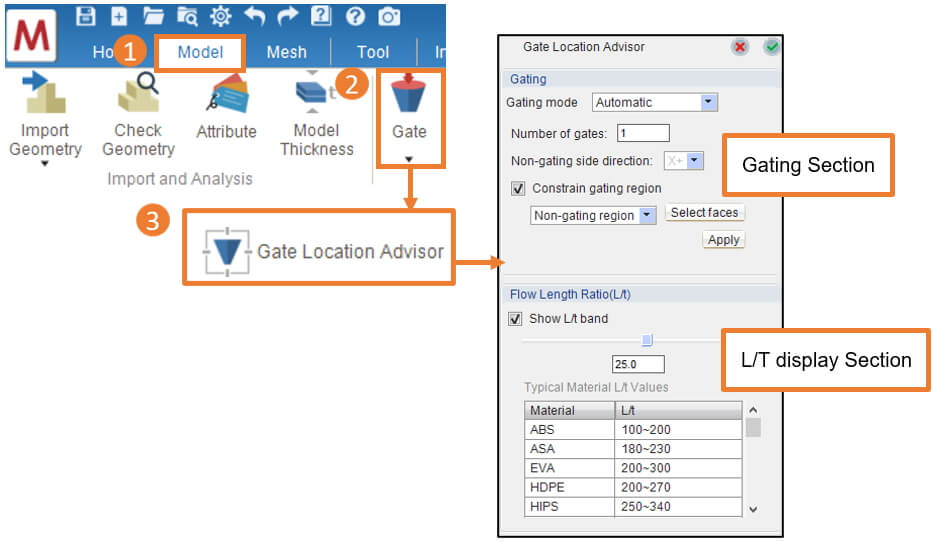
Preparing a Part model in Studio. Under Model tab, click Gate and Gate Location Advisor to launch the tool.
Step 2-1. Gate location advisor operation process
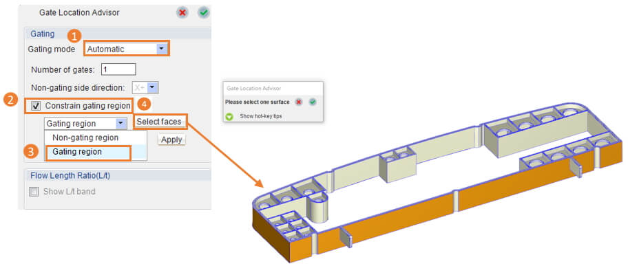
In the Gate Location Advisor, select Gating Mode: Automatic for optimized gate design with user-specified Non-gating side direction or Constrain gating region. As the following example, the user should have the gating surface on the side only, Check the Constrain gating region, and select Gating region. Then, click Select faces and select on the model as shown below.
Note :
- In Manual mode, users can click Add/Move/Remove to assign the gate position manually.
- The Non-gating region and Non-gating side direction often refers to the mold core side (movable) where gating should be avoided.
- In Studio, there are only 6 orthogonal directions for setting the Non-gating side direction. If there are other directions required, users should set them through the API.
Step 2-2. Set the number of gates
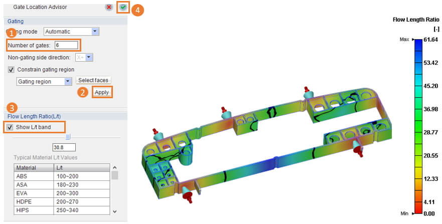
After selecting the gating surface, the user can enter the number of gates and then click Apply. The tool will then calculate the appropriate gate position according to the conditions entered by the user. In addition, click Show L/t band which can help the user check whether the gate position is appropriate or not and approximation of the melt front through the Flow Length Ratio(L/t). After completing the design, click the green tick in the upper right to complete the gate location design.
Note :
- The maximum number of gates is 10.
- If there are existing gates already assigned, Gate Location Advisor will consider them, and then calculate to add additional gates using the number specified to make recommendations.
Step 3. Result
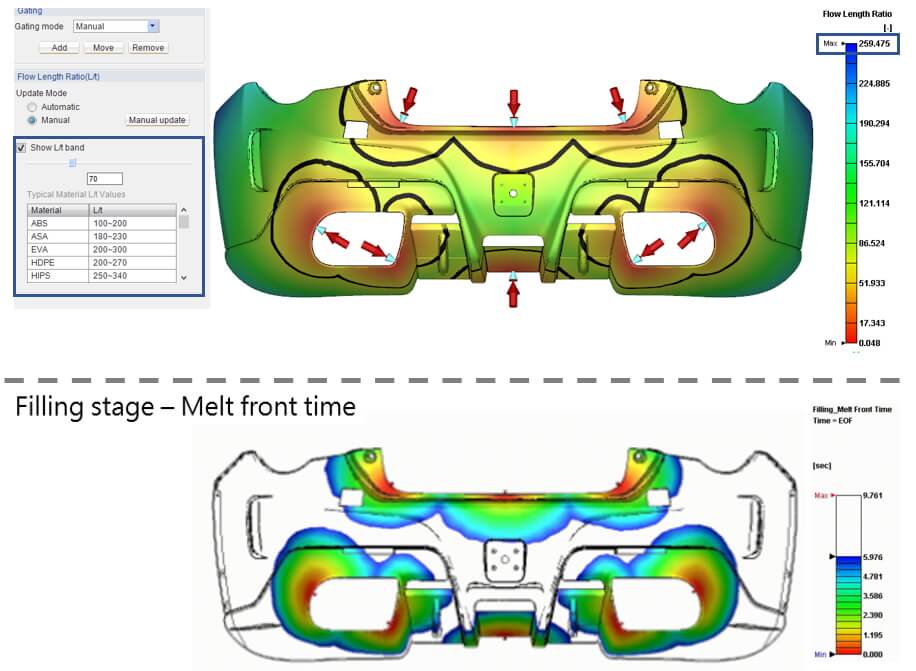
The user can check whether the gate location and quantity are appropriate using the Gate Location Advisor and the show L/t band. For example, as the first figure below shows, the longest flow-length ratio at the gate location is 259.475. If the material is HDPE, then the number of gates conforms to the typical flow length ratio range. In addition, users can drag the flow length ratio to observe the positions of each gate at different flow length ratios (black lines), to predict the position and strength of the weld line before simulation. This can help users determine whether the position and number of gates are appropriate. The 2nd figure below is the melt front time simulated by solver after analysis, so through comparison we can see the prediction from show L/t band function is quite reliable.
Note: If the user wants to adjust the gate position, they can add/move/remove the gate position in manual mode.