
Technical Validation Department.Senior Engineer.Mars Lai
Modern plastic product designs tend to pursue multi-functionality and aesthetic appeal, leading to increasingly complex mold structures. For part inserts, the pre-processing process—mesh generation in particular—has become a significant challenge. The most difficult part in Multi-Component Molding (MCM) simulation lies in handling contact faces between different materials, such as double-shot molding or metal inserts. The simulation accuracy often depends on how precisely these contact faces are dealt with.
Engineers often face a trade-off: either opting for non-matching mesh to save modeling time or pursuing optimal physical continuity at the cost of a tedious manual mesh alignment process. Moldex3D 2026 now introduces Divide Polysurfaces to facilitate the handling of contact face meshes, allowing for a smoother mesh generation process.
Defining & Dividing Geometry
Step 1: Preparing the Model
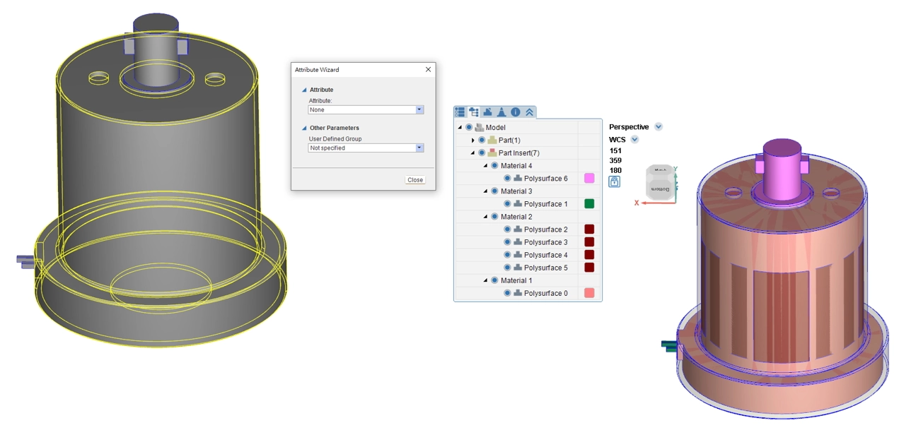
In the Model Tab, click on Import Geometry to select the required geometry files and click OK. The geometry models for the part (polysurface) and runner (curve) will be imported and displayed in the display window.
Step 2: Model Setting
Double-click the polysurface to open the attribute setting and set the outermost polysurface as Part. Select other polysurfaces, click Attribute in the Model Tab, designate them as Part Insert, and click Close to complete the setting.
Step 3: Configure the Cooling Path and Set Inlet/Outlet Points
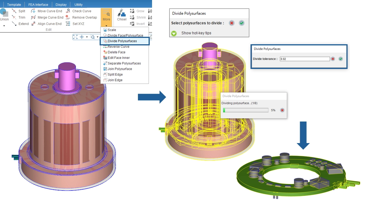
Click the Divide Polysurfaces function in the Tool Tab. Select the entire model, set the Divide Tolerance, and click OK to begin dividing polysurfaces.
Constructing Matching Mesh
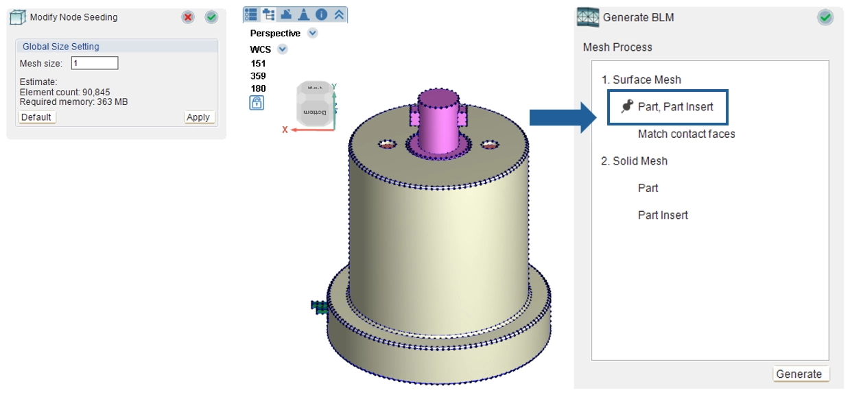
Step 1: Seeding
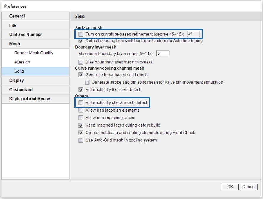
In the Mesh Tab, first confirm the mesh type as Solid, then perform seeding. Please note the following during seeding:
- Seeding density shouldn’t vary too much. Do not check “Turn on curvature-based refinement.”
- If the mesh count is high, it is NOT recommended to check “Automatically check mesh defect” so as to prevent automated updates to defect tree during mesh fixing.
Step 2: Generating Surface Mesh
MCM models require matching mesh. Enter the BLM Wizard and pin it at the first step to generate the surface mesh.
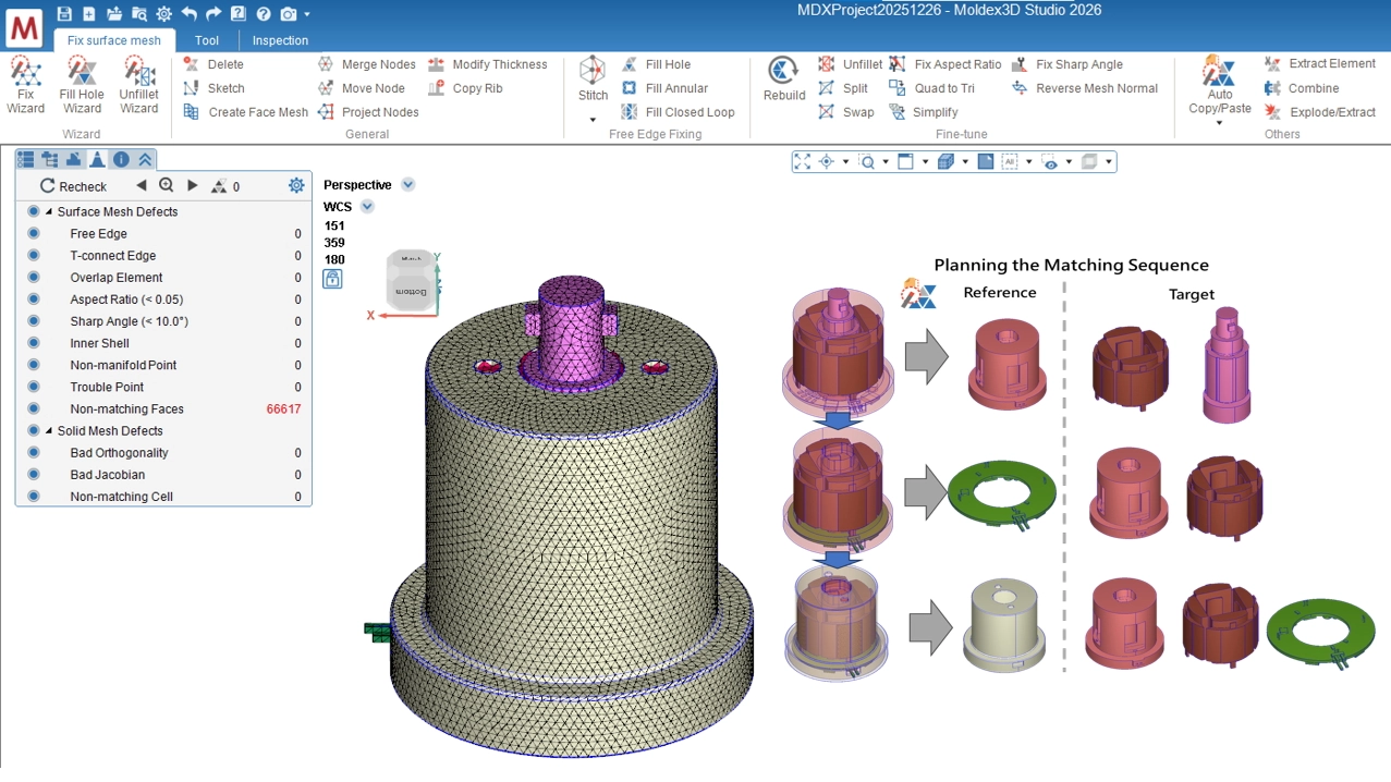
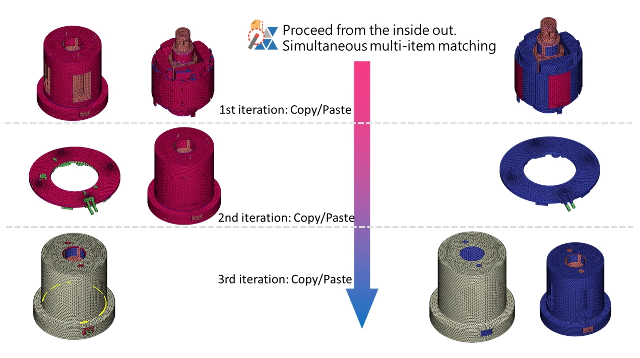
Step 3: Matching Surface Mesh
Before constructing matching mesh, decide the matching sequence for different insert meshes. Match internal inserts first and proceed from the inside out.
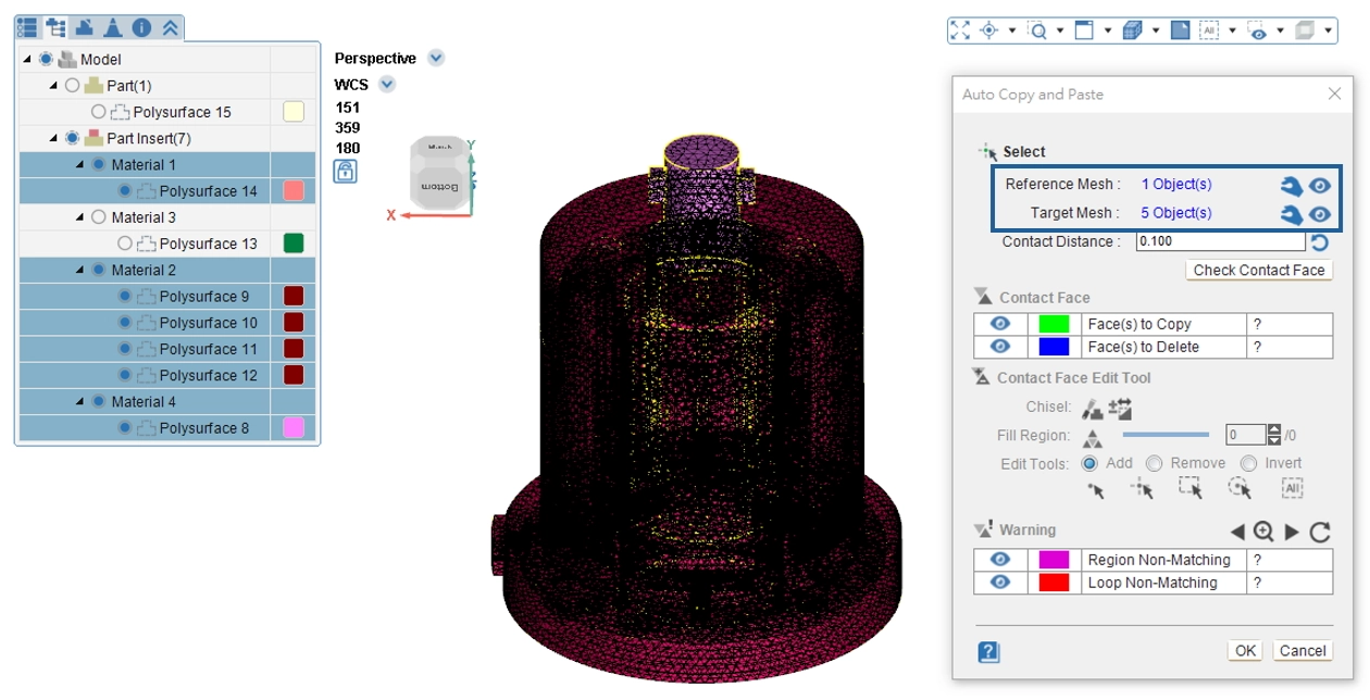
Step 4: Auto Copy/Paste
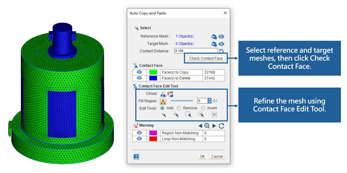
Use the Auto Copy/Paste function. First select the reference mesh, then select the target mesh, and click Check Contact Face.
Step 5: Contact Face Edit Tool
Warnings will show areas and edges with non-matching mesh. Use the Contact Face Edit Tool to fine-tune the mesh.
Step 6: Completing Surface Mesh Matching
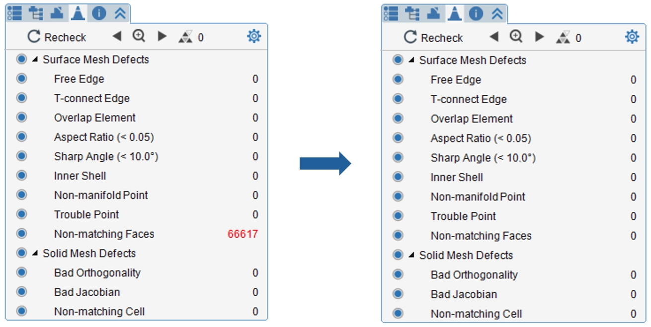
Recheck surface mesh defects. The faces are successfully matched when the Non-matching Faces error count is zero.
Step 7: Final Check
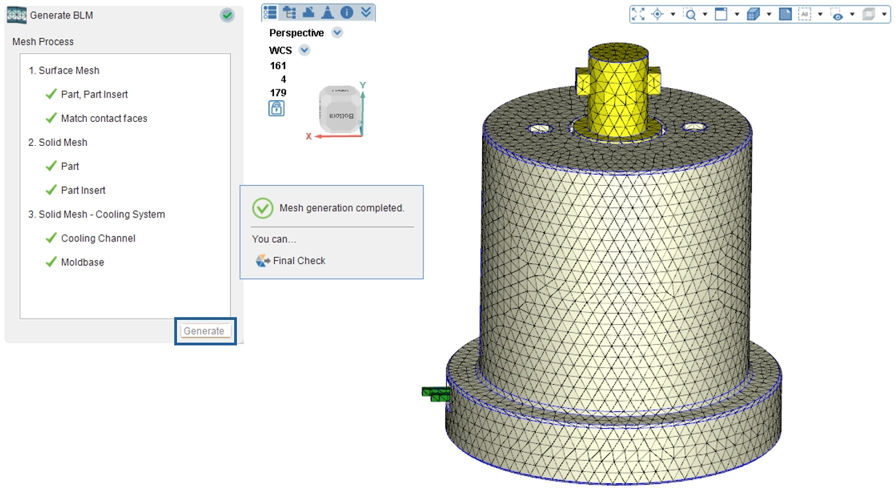
Return to the Mesh Tab and click Generate. Click the Generate button in the wizard to continue mesh generation. When all mesh items are complete and the Final Check button appears, click Final Check to save the mesh file.
Divide Polysurfaces Features
- Divide contact faces more efficiently.
- Provide a clearer progress bar during execution to keep users informed of current progress.
- Able to click the cancel button on the progress bar to suspend execution.
- Do not need to repeatedly execute the Divide Face/Polysurface function regarding different target geometries.
- Automatically determine which polysurface geometries are in contact within the user-input tolerance and conduct dividing.