Philip Chang, Principal Engineer at Technical Support Division of CoreTech System (Moldex3D)
Plastic optical components are widely used in photoelectric, electronic devices, and automobile industry to replace traditional glass material due to high cost-performance ratio and applicability. However, the extreme product design with large thickness and a high thickness ratio causes high risk of defects such as jetting, air trap, sink mark, and void via injection molding. Excessive volume shrinkage makes it challenging to precisely control product specifications. Increasing manufacturing efficiency is also challenging due to excessively long cooling time.
Multilayer injection molding is one of the solutions for this extreme design of optical products. It decreases the challenge of injected product with large thickness by separating the overall product into stacked A-B layers and injecting sequentially. Moldex3D supports predicting the flow-induced residual stress and thermally-induced residual stress of A-B layers during multi-component injection molding, and it estimates the fringed order and fringed pattern of overall product. Optic analysis of multiple component molding via Moldex3D:
First shot (A layer) simulation
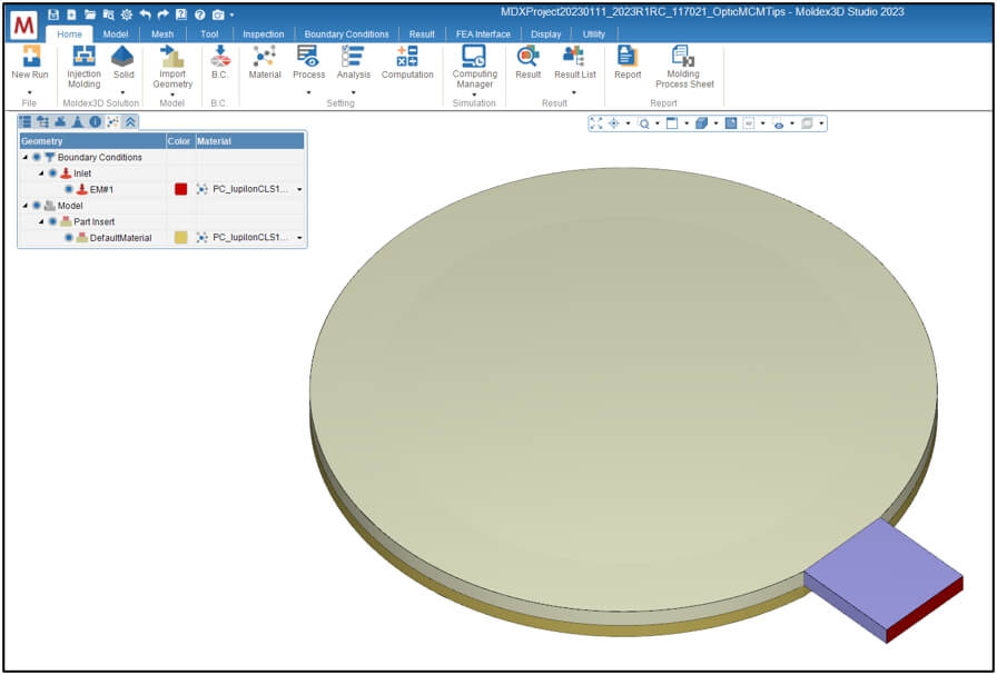
Step1: Prepare Model and Simulation Run for the 1st shot
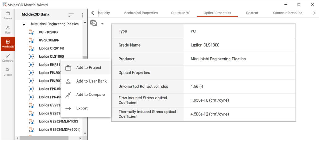
First, in Moldex3D Studio, prepare a run with Molding Type of Injection molding for the first shot (A layer). The material selected must contain Optical Properties including Un-oriented Refractive Index, Flow-induced Stress Optical Coefficient, and Thermally-Induced Stress Optical Coefficient.
Step2: Analysis and Computation Parameter Setting for the 1st shot
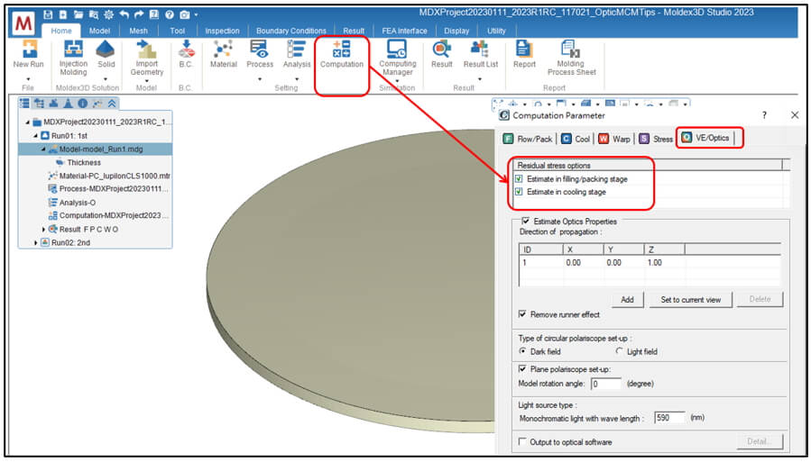
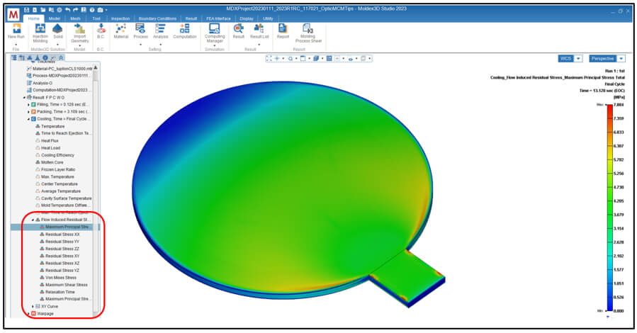
In VE/Optics tab of Computation Parameter, check Residual stress options Estimate in filling/packing stage and Estimate in cooling stage. Finish all analysis setting and submit the run for calculation. After calculation completed, the Flow-induced Residual Stress will show in the results of Filling, Packing, and Cooling.
Second shot (B layer) simulation
Step3: Prepare Model and Simulation Run for the 2nd shot
Prepare a new run for the second shot. The model should contain part of second shot (B layer) and part insert (A layer). Same as the first shot simulation, the materials of part and part insert must include Optical properties. The geometry and material of part insert must also be identical to first shot.
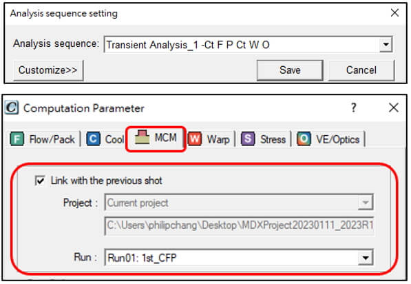
Step4: Analysis Setting for MCM and Optics Molding Simulation of the 2nd Shot
In Analysis Sequence Setting, add Optics after Transient Analysis to ensure the optics analysis fully consider the flow induced residual stress and thermally induced residual stress effect.
In Computation Parameter, check Link with the previous shot in MCM tab to consider the injection effect from the first shot and choose the run ID of the first shot in the pull-down menu.
Step5: Set VE and Optics Computation Parameter for the 2nd shot
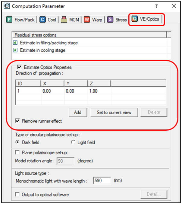
Same as the first shot simulation, check Residual stress options Estimate in filling/packing stage and Estimate in cooling stage in VE/Optics tab. Also, check Estimate Optics Properties below, and click Add to increase an ID to direction of propagation list and input the vector as below which light project to product. For other Optics properties, leave them as the default values in this case.
Step6: Run MCM & Optics Analysis and Check the Results
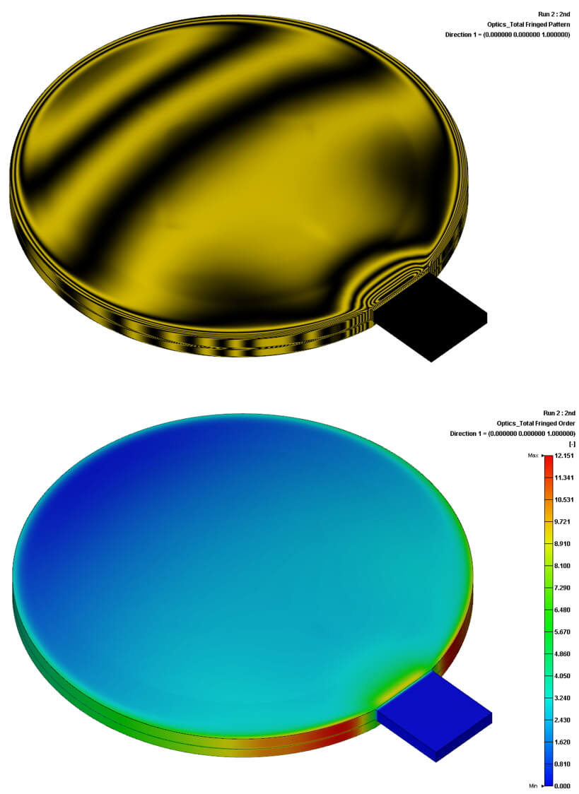
Finish all analysis setting for the 2nd shot and submit it for calculation. After calculation completed, refractive index, retardation, fringed order, and fringed pattern will show in the results of Optics. The Optics results will consider the overall effect of molding and propagation on both part and part insert (Layer A & B).
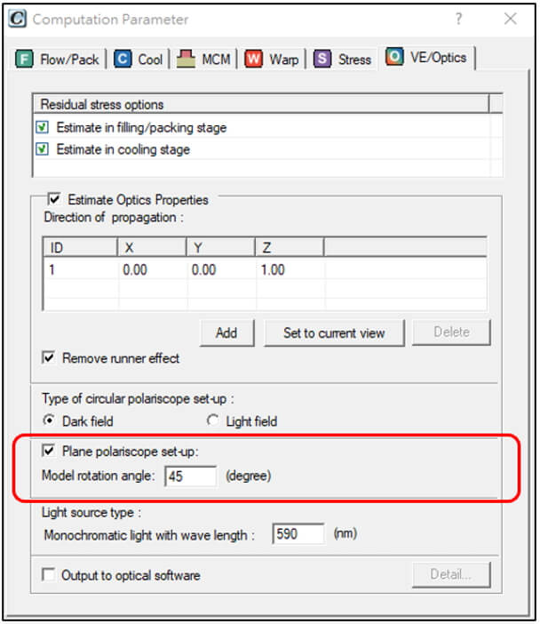
Further analysis – Plane Polariscope Analysis
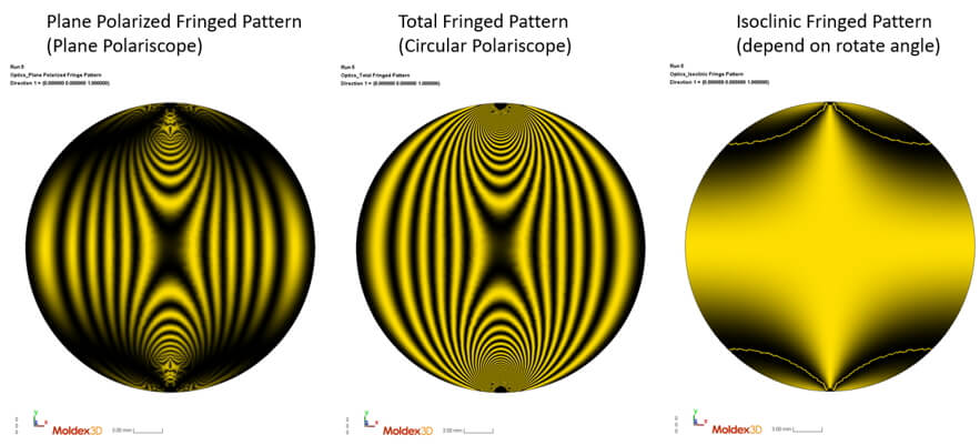
In the standard results of Moldex3D Optics, total fringed pattern shows the pattern examined by circular polariscope, named isochromatic fringes. This pattern will not vary with the rotation angle of part in the plane. For the pattern examined by planer polariscope, it includes both isoclinic and isochromatic fringes. Isoclinic fringes depend on the rotation angle of examined part located in plane.
To obtain plane polariscope fringed pattern in Moldex3D, check “Plane polariscope set-up” in VE/Optics tab of Computation Parameter and input the Model rotation angle in the plane perpendicular to the direction of light propagation.
Plane polariscope analysis results including isoclinic fringe pattern and plane polarized fringe pattern will show in the results of Optics after simulation.