
Cyber-Physical System (CPS) is a key technology in the Industry 4.0 system. The CPS concept in injection molding should be the integration of molding simulation and injection machines. However, there is still a gap between the theory and the actual machine behaviors due to many factors such as mechanical engineering, materials and controller performance. Thus, the integration of the physical world and the digital world is an important issue.
Usually, we regard the response speed of an all-electric injection machine as higher, and a hydraulic injection machine as lower (Fig. 1). We also assume the actual filling speed and packing pressure will be the same as what we set. However, in reality, it will lead to a difference between the theory and actual response result. Fig. 2 shows the speed response result of an all-electric injection machine. The set speed is 90mm/sec, and from the figure we can see the injection speed does not begin immediately. It will gradually reach the set speed after the delay time caused by resistance. When the actual injection speed reaches 95% of the set speed, the machine response speed will decrease until the injection speed reaches the set speed. It is difficult to manually control the speed response rule. is the reason why we need machine identification, is so that the response rule can be included in the analysis.
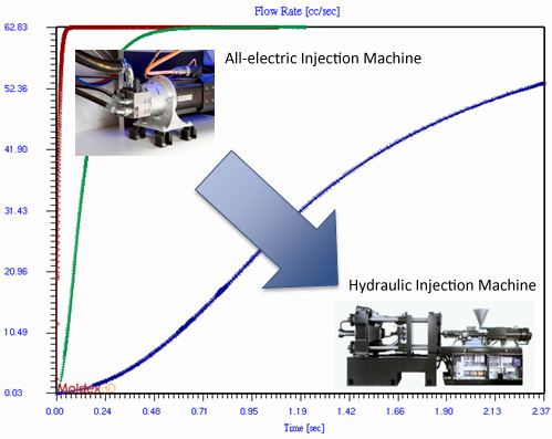
Fig. 1 The machine response difference between an all-electric injection machine and an oil hydraulic injection machine
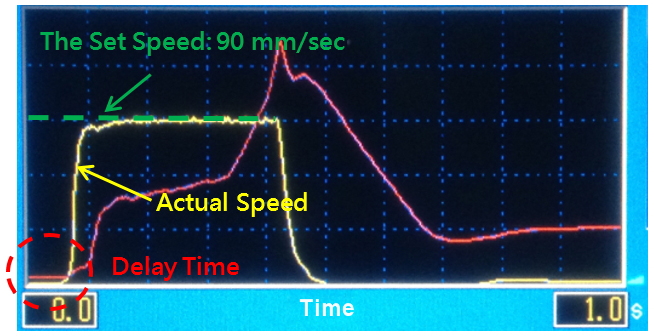
Fig. 2 The speed response changes of an all-electric injection machine
Fig. 3 shows the effects of different speed response settings on the same injection speed (120mm/sec). When the set response time is shorter, the faster it can achieve the set injection speed and vice versa. In addition, even though the set time is the same, neither the injection pressure values nor the time of the V/P switch-over is the same due to the fact that the speed response values are different.
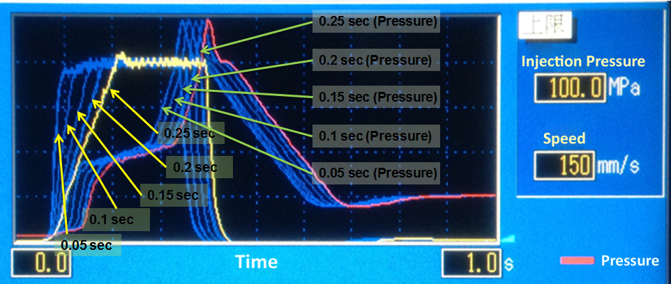
Fig. 3 The effects of different speed response on the time and pressure
In order to evaluate the effects of the actual machine response, Moldex3D collects machine response data based on the experimental methods. The machine response characterization workflow is shown in Fig. 4. Users can choose the injection machine types, molds and materials, and collect the experimental data of different speed and pressure settings. Then, they can identify the response parameters of the machines based on the Control Theory, and apply the data in Moldex3D analysis. After the machine parameters have been collected, users have to put the machine parameter file into the machine database in the Moldex3D Process Wizard (Fig. 5) and choose the machine in the Process Wizard without changing any settings. Moldex3D Solver will then run an analysis based on the actual machine response, enabling more accurate simulation results (Fig. 6).
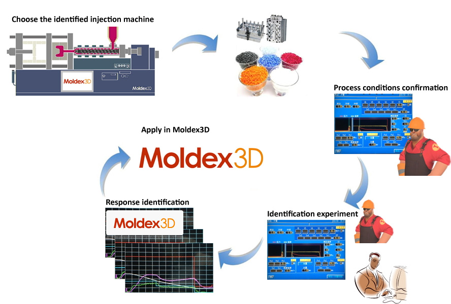
Fig. 4 The experimental workflow of the machine response
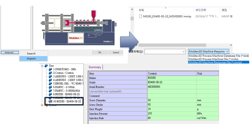
Fig. 5 Input the parameter file into the machine database
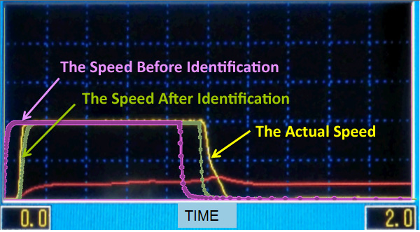
Fig. 6 The speed changes after machine identification
By taking into account the real-world machine response, users can more accurately reflect the real-world manufacturing conditions in simulations. The optimized processing conditions obtained from the simulation can then be directly applied on the shop floor, bridging the gap between simulation and manufacturing.