Annealing is a crucial part of the plastics molding process. The annealing process will heat the material and maintain it at a specific temperature fora while, and then slowly cool down. The main purpose of annealing is to relieve the residual stress. Annealing is also applied to increase the material ductility and toughness of the products and generate a special microstructure.
Moldex3D Stress enables users to observe the product deformation behaviors under the hot oven annealing process. The annealing simulation would then provide the displacement results, Von Mises Stress, Shear Stress, and the Temperature distribution results based on the Warp calculation results. (Fig. 1)
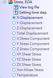
Fig. 1 Result list of annealing analysis
In the Moldex3D R17 version, the annealing simulation also considers the fiber effect on the geometry deformation so that a more accurate warp result can be attained.
Annealing Simulation Considers Fiber Orientation Effect Procedure
Step 1: Mack sure the Run fiber orientation analysis options are enabled in the Flow/Pack tab (Enhanced Solver or Standard Solver) and the Warp tab of Computation Parameter.
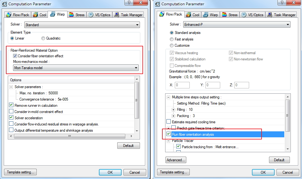
Fig. 2 Computation Parameter setting of Flow/Pack tab and Warp tab
Step 2: The default Micro-mechanics model is the Mori-Tanaka model, and users can choose other models if needed. The Micro-mechanics model of the Annealing simulation follows the Warp tab setting and the model type can be checked the function in the Log file.
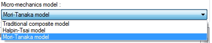
Fig. 3 Three models are available in the Micro-mechanics Model selection
Step 3: In the Stress tab, select the Analysis type as Annealing. Then, run the Stress-S analysis after the standard analysis sequence (CFPCW) simulation is finished.
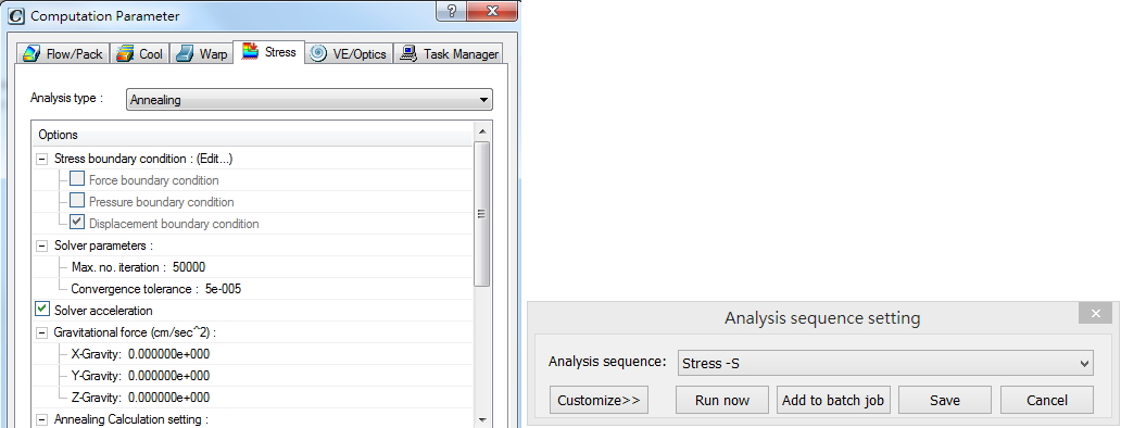
Fig. 4 The annealing setting and starting up the Stress analysis
Note: Users can recheck the Log (*.lgs) file. It records the setting which is synchronized with the Warp simulation. (*.lgw)
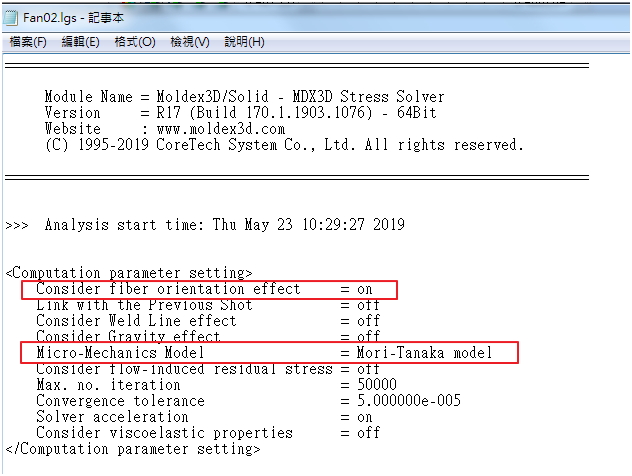
Fig. 5 The annealing information of the Stress log file
Case Study
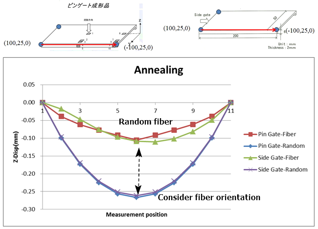
Two sample plates, a pin gate, and a side gate are compared by considering the Fiber orientation effect and with Random fiber orientation consideration. Users can obtain the Z-Displacement result at the end of Annealing (EOA) simulation as shown in Table1. The final deformation of considering the fiber orientation effect is different from the Random fiber orientation consideration in both the pin gate and side gate plates.
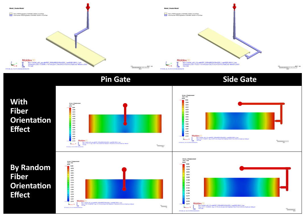
Table 1 Comparing two gate types of plates with Fiber orientation and Random fiber orientation consideration
Fig. 6 is the curves detected by the measure nodes along the red arrow direction and position. It shows that fiber orientation has a significant effect on deformation during the annealing process.