

Edited by Sam Hsieh, Manager at Technical Support Team, Moldex3D
![]()
- Customer: TONG YANG GROUP
- Region: Taiwan
- Industry: Automotive
- Solution: Moldex3D Advanced Package; Flow
TONG YANG GROUP was established in 1952. Nowadays, it has a total of 25 manufacturing plants and 9,307 employees worldwide. Their main products are plastics, sheet metal, cooling fan assemblies, tooling development, and painting products and the corporate mission is to provide the best quality of automotive collision parts for consumers. (Source)
Executive Summary
Tong Yang engineers were tasked with solving aesthetic defects in a plastic fog lamp injection molded part (Fig. 1, 2). Since it is an automotive exterior component, weld lines should be avoided if possible. In addition, weld lines should not appear on the surface of the locking component as well. Tong Yang engineers used Moldex3D to understand how runner layouts can affect the position and the angle of weld lines. In addition, Moldex3D assisted Tong Yang in optimizing wall thickness to solve air traps, successfully solving aesthetic problems in the fog lamp part.
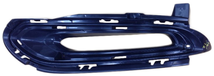
Fig. 1 The fog lamp part in this case
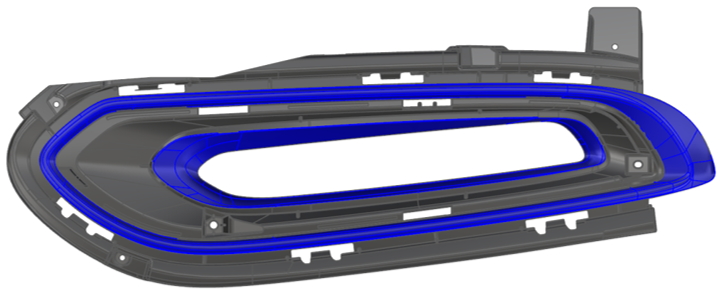
Fig. 2 Blue color indicates the visible appearance areas
Challenges
- Avoid weld lines to occur in the visible appearance areas
- Figure out an effective revised design to resolve the air trap issue
Solutions
Moldex3D allowed Tony Yang engineers to analyze various gate locations to optimize fill patterns to avoid weld lines in the part surface. Moreover, based on Moldex3D’s flow analysis results, Tong Yang engineers were able to detect the air trap in the core side and make necessary design changes, including adjusting the wall thickness, to resolve the air trap and improve the weld line locations.
Benefits
- Solved surface defects, including air traps and weld lines
- Avoided costly mold rework
- Accelerated design decision-making
Case Study
The development of this fog lamp part was split into design and mold trials, two stages. Moldex3D simulations are performed in both development stages for different purposes. During the design stage before making the mold, the main purpose was to verify the gating design and predict the potential cosmetic defects. The gating design verification had 3 types to be simulated that combined different gate numbers, position, and runner layout. The design decision-making criterion was about the number of cosmetic defects of the weld line and air trap. The least defect design was used for further cosmetic defect optimization works. After the mold was made and the first mold trial was done, the simulation results were validated with the actual molded part. In addition, the observed defects from the mold trial were analyzed for seeking the root cause and effective solutions (Fig. 3).
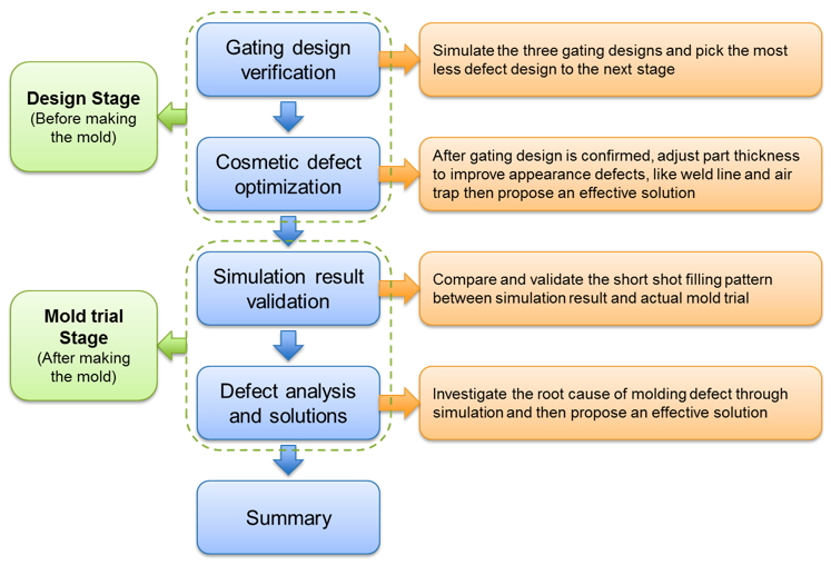
Fig. 3 Main purpose in different development stages
The gating design verification was the first task utilizing Moldex3D. As shown in Fig. 4, Type A has a single gate located on the lower middle of the part. The gate number in design Type B is the same as Type A, but the gate location is on the lower right of part. The last design Type C has two gates located on the left and right sides. After completing all designs’ analyses, the weld lines and air traps that occurred on the visible appearance areas were counted for the final gating design decision making.
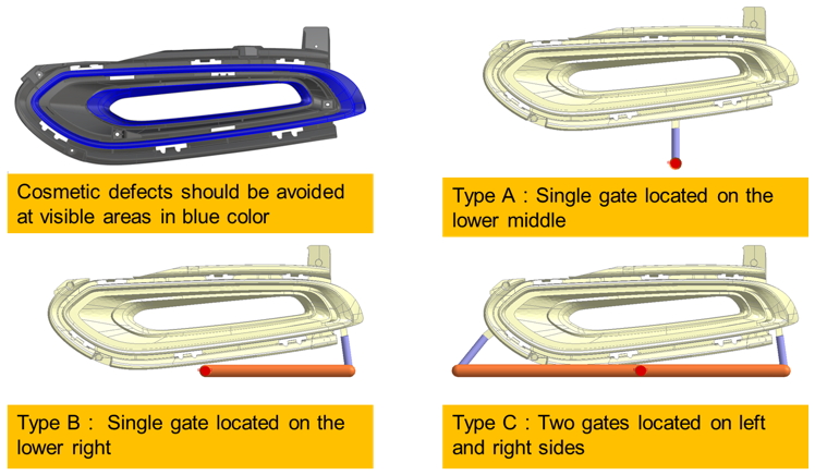
Fig. 4 Appearance quality requirement and the three types of gating design
According to the comparison table of the weld line and air trap from the analysis results in Fig. 5, Type B has the least defects of the weld line and air trap, so it was used for further cosmetic defect optimization works.
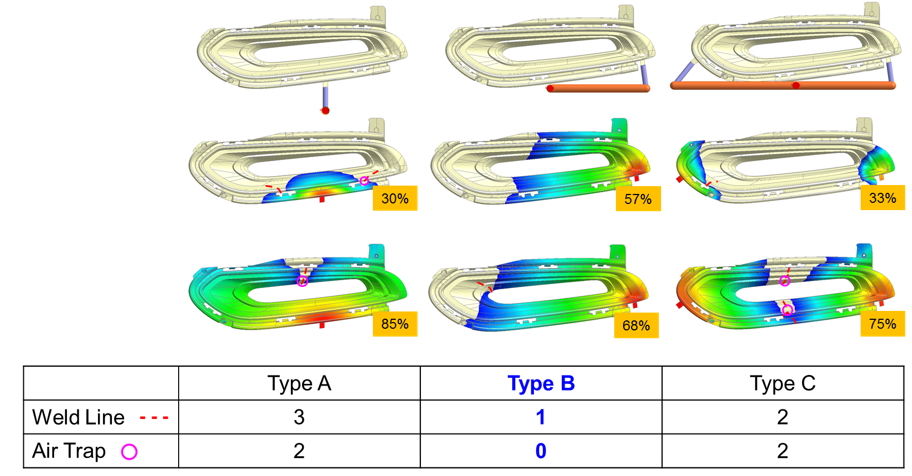
Fig. 5 The prediction comparison between 3 types of gating design
The welding angle is one of the indexes that commonly used to compare and judge the weld line quality. The welding angle in the original part thickness design is around 120 degrees. After part thickness design optimization as shown in Fig. 6, the welding angle has been increased from 120 to 140 degrees which means the weld line is shorter and less visible.
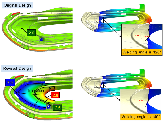
Fig. 6 The part thickness optimization for improving weld line quality
After the mold was made and the first mold trial was done, the simulation results were validated with an actual molded part. As shown in the comparison pictures at the different filling percentages (Fig. 7), the simulation result was consistent with the actual short shot part.
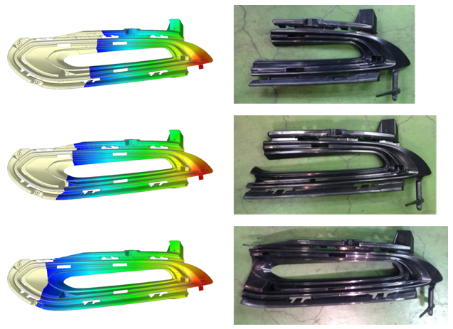
Fig. 7 Filling pattern comparison
However, an air trap was observed on the part surface in the first mold trial. The air trap occurs in a visible area on the cavity side of the mold where is not allowed to implement any venting slot. The melt front shows the same filling pattern that corner region flows faster than surrounding regions. The root cause is about the geometry feature of fillet makes the part thickness becomes thicker (3.5 mm) compared to the main thickness (2.5 mm), so the thicker region flows faster since it has lower resistance like a flow leader.
The solution that core-out part thickness at 3.5 mm region is proposed and verified with Moldex3D simulation (Fig. 8). According to the melt front time result with the core-out model (Fig. 9), there are two extra weld lines occur. However, the two extra weld lines are located at invisible regions, so it is acceptable.
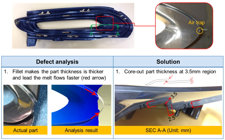
Fig. 8 Defect analysis and solution
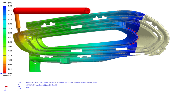
Fig. 9 Filling pattern of core-out model
The new core-out design is taken to modify the mold. The air trap and weld line issues are checked again after the mold trial and the outcome is consistent with previous simulation results. The air trap can be eliminated by doing core-out the part thickness and the additional weld lines are acceptable since they are located at invisible regions (Fig. 10).
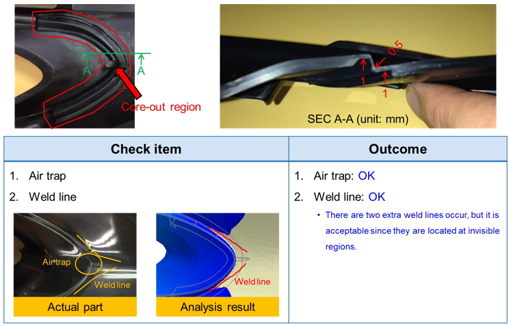
Fig. 10 Solution implementation and validation
Results
Moldex3D simulation works are involved at the beginning of gating design verification and defect analysis after mold trial. The prediction results of final gate design are constantly to actual short shot samples after the first mold trial. However, uneven part thickness causes an air trap issue. Venting slot is not possible in this case since the air trap location is on the appearance surface. Moldex3D simulation is utilized again to analyze the defect and validate the core-out solution in part thickness to avoid costly mold rework. Lastly, Moldex3D assisted Tong Yang in optimizing wall thickness to solve air traps, successfully solving aesthetic problems in this fog lamp part.