
iMFLUX operates in a mode where a fixed injection pressure (low pressure ) is applied. During the filling process, a consistent injection pressure will be maintained. By controlling the plastic pressure throughout the molding process, the molten plastic is delivered to the mold cavity without stalling or stagnation, allowing the flow front to advance continuously under constant pressure. iMFLUX automatically adjusts the velocity, resulting in the advantage of a more consistent flow front. Due to the utilization of lower injection pressure, the peak pressure during the injection process is lower compared to the peak pressure in traditional velocity-controlled injection molding, as shown in Figure 1. The lower injection pressure helps to minimize product quality issues, and by controlling the pressure, it stimulates an early transition to the packing phase, which helps in reducing cooling time and thus the overall cycle time. To effectively control the pressure inside the mold cavity in iMFLUX, pressure sensors with PFA (Process Factor A, the pressure control coefficient) setting are installed within the mold. Controlling the molten plastic pressure through PFA enables a precise control of the injection process.
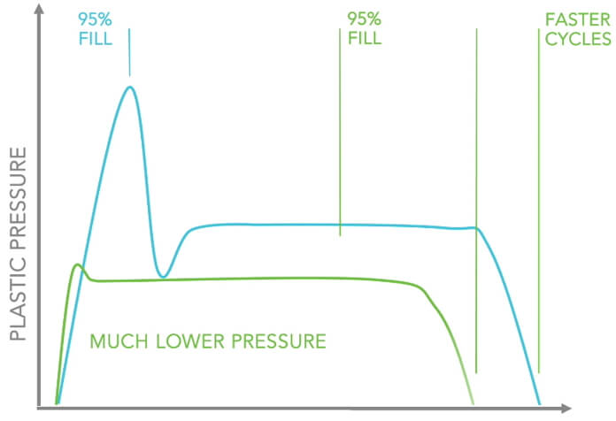
Figure 1. Comparison of traditional injection process(━━━) and iMFLUX process(━━━)
(Reference: https://www.imflux.com/)
When utilizing the iMFLUX process, selecting the optimal injection pressure and determining the appropriate placement of mold sensor for PFA control parameters are important and crucial. In the past, users utilized a trial-and-error approach to find feasible value. Now, using iMFLUX process in Moldex3D can enable them to replicate the process through simulation, as shown in Figure 2. Users can conduct early analysis before implementing the process, and once adopted, they can use simulation results to determine the optimal molding pressure and avoid ineffective excessive injection pressure. With the integrated function in Moldex3D, users can predict melt behavior and identify the best location for inner mold sensors to find PFA control parameters, achieving optimal pressure adjustment.
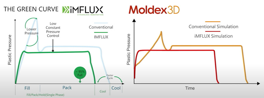
Figure 2. Moldex3D implementation of iMFLUX process simulation
Taking a boxed product for an example, users can utilize the Create Run(s) Wizard in Moldex3D to quickly set up multiple analyses with different pressures by selecting the maximum packing pressure as shown in Figure 3.
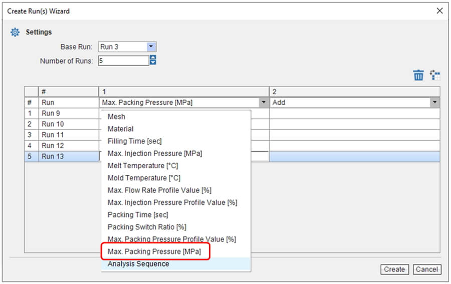
Figure 3. Multiple analysis setting
From the analysis consequence, it is observed that when the pressure is set at 25MPa, the product is adequately filled, as shown in Figure 4. Therefore, there is no need to set the injection pressure beyond 25MPa. Moldex3D allows users to determine feasible pressure condition before conducting mold trials, reducing the waste of material and energy during trial-and-error.
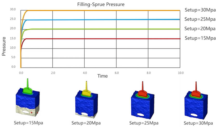
Figure 4. Products of filling results at different pressure
In the selection of positions for setting PFA controlling parameters, one advantage within CAE is the ability to set multiple sensor nodes in candidate positions, approaching the placement of multiple sensors in the product. Through CAE analysis, the optimal sensor location can be obtained for PFA control, as shown in Figure 5. After the analysis is completed, users can utilize the Summary table in Moldex3D to observe analysis results for different sensor nodes, allowing them to find the appropriate sensor position. In this example, after the melt passes Sensor 1 or Sensor 2, the PFA control can be initiated. As shown in Figure 6, Sensor 1 provides better results in shrinkage and warpage and lower clamp force for the product in simulation. Therefore, it can serve as a reference for the installation position of subsequent sensors.
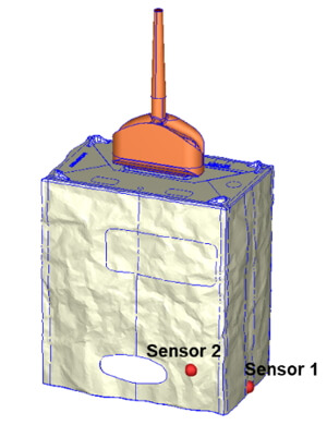
Figure 5. Setting multiple virtual sensor nodes
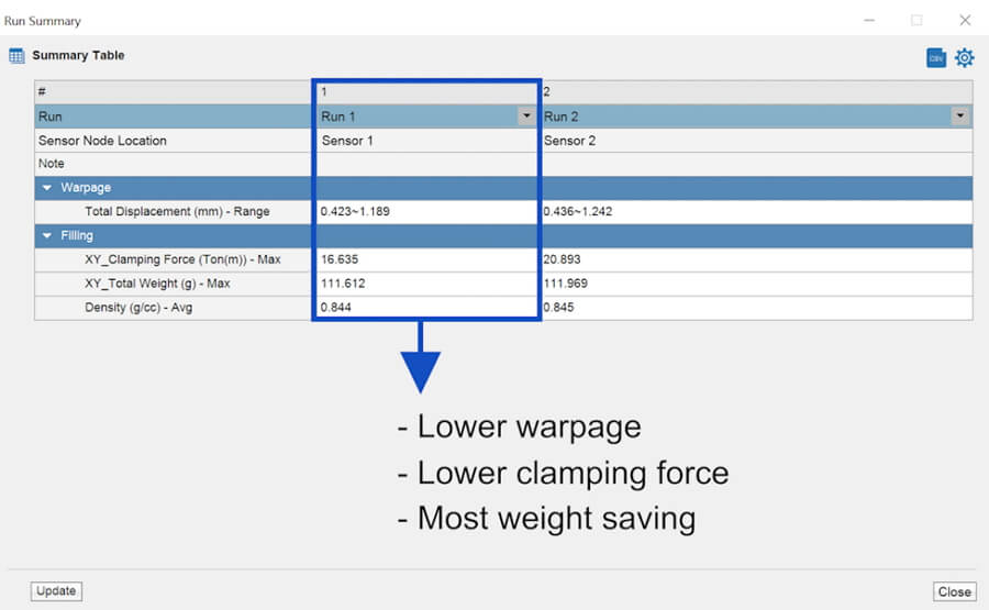 Figure 6. Analysis outcome of different sensor nodes
From the PFA setting in Moldex3D, the analysis results can show the variation of melt pressure under different PFA settings. Figure 7 separately illustrates the pressure variation when PFA is set to 0.5 and 0.1. This information can be used to evaluate appropriate PFA coefficient setting value before actual production.
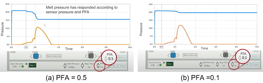
Figure 7. Pressure variation using different PFA coefficients
iMFLUX process can effectively reduce the waste cost due to trial-and-error methods and shorten the trial runs with the analysis outcomes, which speeds up the time to mass production. In the past, when users employed iMFLUX for product manufacturing, they had to rely on trial-and-error to find the appropriate injection pressure. Selecting the suitable sensor placement before production has always been a challenging for users but now, with the iMFLUX process simulation abilities in Moldex3D, users can assess the benefits and evaluate the adoption of the iMFLUX process. When iMFLUX process is implemented, Moldex3D simulation capabilities can help users find optimal molding pressure and appropriate placement of internal pressure sensors in the mold to analyze the effect of different PFA controls.