Runner flow balance has been one of the most essential factors when it comes to a successful mold design. However, achieving a balanced flow pattern is not always an easy task for many mold designers. When polymer melt flows through the runner, a frozen layer will be created along the flow path on the runner’s wall, resulting in a smaller cross-sectional area for the flow to pass through. There are various factors that may influence the thickness of a frozen layer such as injected speed, mold temperature, or material characteristics, etc. In addition, the different design arrangement for the runner’s diameter and layout will add to the level of difficulty for achieving a flow balance.
Under the effect of these intricate influential factors, young mold designers may find it difficult to find a solution to resolve the flow issue without resorting to the help of an experienced mold maker. Besides, the overall development time can be shortened when a CAE tool is applied to resolve the issue. However, in order to obtain the most optimal runner system design, a series of possible try-outs in a CAE simulation tool before one can find the most ideal molding scenario is still inevitable in this process.
Generally speaking, the goal of achieving a balanced flow in a hot runner system with trial-and-error method can be achieved through two ways:
- To enlarge the geometric size of the hot runner system in order to lower the pressure drop in the cavity.
- To ensure the symmetric geometry design of the hot runner system in order to adjust the gate and the runner’s size.
In recent years, due to the unwanted waste on time and resources of a mold trial, many mold designers have turned to the aid of CAE virtual molding technology in order to save costs and reserve energy. A virtual molding analysis can be attained using the CAE tools to analyze the important production data including part geometry, runner system layout and mold geometric design. As a result from a CAE analysis, mold designers are able to attain valuable molding information such as temperature distribution in hopes of helping them to identify the potential problematic areas as well as to optimize the hot runner design further.
Moreover, as the product design continues to advance in modern product development process, so does the design of a hot runner system; the more complex the hot runner design is, the more time it needs for attaining a detailed Advanced Hot Runner analysis. Especially for a multi-cavity mold design; though, the geometry and size of each cavity is the same, it is difficult to attain the most optimal filling result. In order to design an effective hot runner system that fulfills the lightweight design concept and achieves the desirable pressure drop range, it needs numerous attempts in CAE Advanced Hot Runner simulation before the most optimal design can be attained. On an average, five or more design changes are required in this process before achieving a satisfactory analysis result. Thus, the time spent on simulation has taken too much time in the overall product development process.
To address the above issue directly, Moldex3D is going to roll out a new feature—Hot Runner Steady (HRS) Analysis in the upcoming R14 version in aim of shortening CAE analysis and design optimization time (See Fig. 1). Moldex3D’s solver will conduct a HRS Analysis based on the layout of the hot runners and the flow rate of each gate can be attained as a valuable reference for users to understand the flow behavior. Through HRS analysis, users are able to detect the potential flow balance issue at the early design stage in order to make appropriate design adjustments; and along with a detailed Advanced Hot Runner Analysis, users are equipped with powerful tools to fully examine and optimize all aspects of their hot runner design, which ultimately leads to a successful hot runner design.
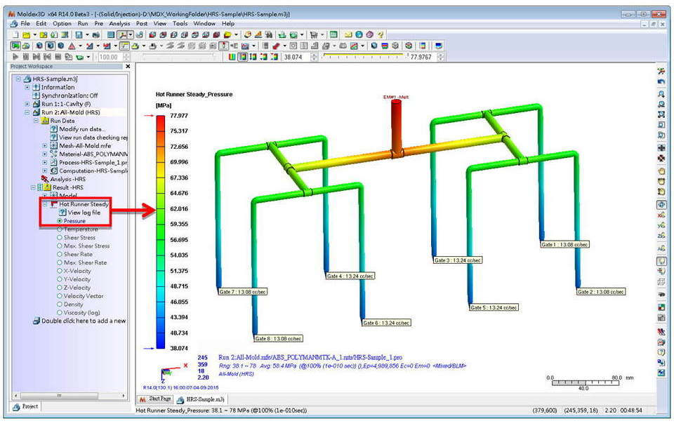 Fig. 1 Moldex3D Hot Runner Steady (HRS) Analysis
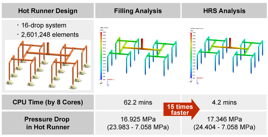
For example, in a 16-drop hot runner system (See Fig. 2), when using a detailed Advanced Hot Runner filling analysis, the computing time would take up to an hour as opposed to merely 4 minutes when using HRS Analysis. In other words, with HRS analysis, the overall improvement on the analysis time can be as great as 15 times faster. In addition, the HRS analysis on the pressure drop predication (17.346 MPa) is closely related to the Advanced Hot Runner filling analysis (16.925 MPa) with only less than 1 MPa in difference.
In summary, with HRS Analysis, users not only can benefit from the true 3D simulation accuracy, but also enjoy a much faster computing process (CPU) time. It raises the possibility of including more design changes in limited CAE simulation time in order to help users speed up their hot runner system development time and ultimately contributes to a major cost saving on mold-reworks and material use.