
In modern plastic product fabrication, multi-component molding (MCM) has been widely applied to diversify product design and simplify the assembly process. Ideally, MCM is a process in which two or more materials, or same material with different colors, or recycled and raw materials, are injected into the mold to produce the product. The product not only combines multiple colors, but also multiple functions such as a combination of soft skin / hard core. The MCM process faces many challenges when used in the real world. First, there are a variety of cavity interchangeable mechanisms and multiple plastication unit setups to choose from. Moreover, the general rules for a single material molding cannot directly apply to MCM. Finally, due to its complicated nature and the unclear physical mechanism for the MCM process during injection, conventional trial-and-error methods have their limitations in terms of their ability to effectively catch crucial factors that compromise product quality[1-8].


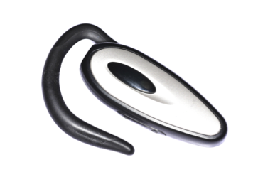
Fig. 1 Multiple functions at one product: (a) multi-color in cosmetics packaging,
(b) in-mold assembled in toys, (c) earphone hook
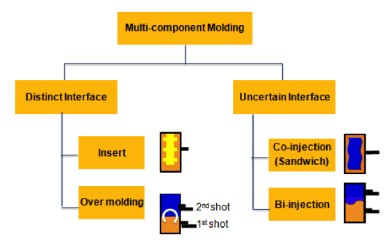
To get a clearer understanding of the way this works, we can categorize the other diversified MCM processes as shown in Fig. 2 as two groups. The first group is the most common process which produces products with a distinct interface. This includes insert molding, over-molding, and sequential multiple shot molding. The second group has an uncertain interface between the two materials. This indistinct interface poses a great challenge for the part designers. The designer must speculate the correct gating location in order to get desired material distribution. Usually this can only be done through molding trials and the geometry complexity of the part is also limited. Co-injection (sandwich) molding and bi-injection molding fall into this group. Also these processes require coherent movement of the injection and nozzle shut-off; which complicates the mold design and injection machine / barrel design.
 Fig. 2 Multi-component molding processes can be divided as: (left) with distinct interface systems,
(right) with uncertain interface systems
Therefore, to resolve the complicated nature and the unclear physical mechanism of the MCM processes, CAE mold filling simulation may become a very powerful tool for problem diagnosis and design validation. For example, a touch pad was originally developed through combining separately injected pieces. This creates less warpage, but causes the part to suffer from poor interfacial bonding strength. Through the use of the overmolding process (Fig. 3a), interfacial strength has been improved. However, serious warpage problems can easily occur. This is due to the heat accumulated on the interface between the two materials (Fig. 3b). The original design and process conditions in single piece injection molding cannot directly apply to the MCM. The warpage problem is resolved through new product designs and different processing conditions [1-4].
a.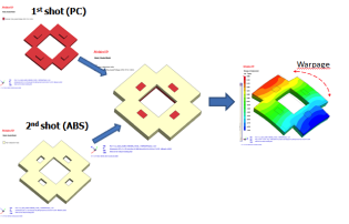 b.
b.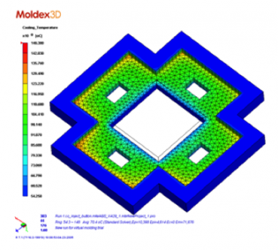 Fig. 3 Touch pad development using multi-component molding processes: (a) through mold rotation, two materials touch pad is fabricated with a significant warpage problem, (b) the warpage is due to heat accumulated along the interface between two materials
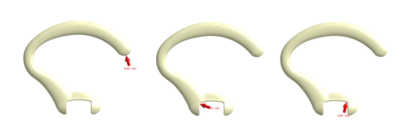
Furthermore, most skin/core material combines soft touch skin and hard core, virgin skin/recycled core, and unfilled skin/ fiber-reinforced core, in commodity, automotive, and structural applications using the co-injection molding process. The main challenge faced today is controlling the material spatial distribution inside the cavity [5-8]. For example, Fig. 4 shows the earphone hook design. The hook connects the phone and microphone assembly. The design has a flexible soft skin to provide better feel while in contact with the ear and should have enough stiffness to withstand deformation. The prior art combines PP as the core and TPE for skin using the overmolding process. The co-injection process was later tested for a simplified workflow and a better joining strength between the materials. During the process engineering stage, it is unclear what the skin/core ratio should be. Fig. 5 shows the CAE results. According to the prediction, a 50% skin ratio will create a core breakthrough leading to defects. A 70% skin ratio is expected to have a better skin/core ratio, but unfortunately this great of a warpage level leads to functional problems. The simulation tool suggests modifying the gate locations as shown in Fig. 6. One design leads to a very low core-filled area at the lock region. Harnessing the aforementioned core break-through behavior will resolve this issue nicely. While keeping the 40% skin ratio, break through happened at 0 .07 sec. And after the break through, the hook portion has the harder PP material to provide better mechanical strength to fit the specification.
a.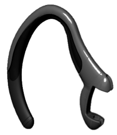 b.
b.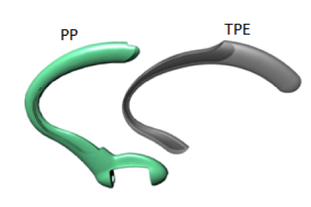
Fig. 4 Earphone hook: (a) geometry design; (b) made PP for core and TPE for skin by the overmolding process
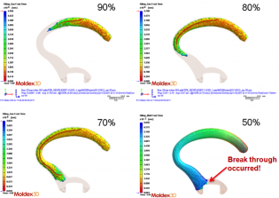 Fig. 5 The co-injection process for ear hook development: 50% skin ratio is to be broken through. A 70% skin ratio is expected to have a good skin/core ratio, but failed to fit the specification for warpage
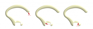 Fig. 6 CAE helps to make gate relocation validation
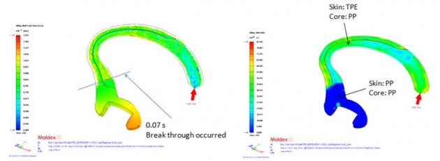 Fig. 7 (a) Reconsider 40% skin ratio: break through happened at 0 .07 sec; (b) after break through, PP material was used on the hook portion to provide better mechanical strength and to fit the specification
Summary
Multi-component molding (MCM) is widely applied in modern product development. However, due to its complicated nature and the unclear physical mechanism, a conventional trial-and-error method cannot catch crucial factors effectively. Today, no matter what kind of overmolding system (with a distinct interface), or a co-injection system (with an uncertain interface), CAE can prove to be a very useful tool for design validation in optimizing gate locations, evaluating the maximum core ratio with or without causing break through, and estimating shrinkage and warpage concerning the interaction between materials.
Reference
1. US patent #3,051,994.
2. Multi-material Technology, Battenfeld.
3. Web source https://www.engelmachinery.com
4. Chao-Tsai Huang et al, SPE ANTEC, 1888-1892 (2006).
5. P.J. Garner and D.F. Oxley, British Patent 1,156,217 (1971).
6. V. Goodship and J.C. Love, Multi-Material Injection Molding (2002).
7. R. Seldén, Polymer Engineering & Science, 40, 1165 (2000).
8. F. Ilinca, J.F. Hetu, and A. Derdouri, International Journal for Numerical Methods in Fluids, 50, 1445 (2006).