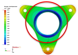
- Customer: Lite-On Technology Corporation
- Region: Taiwan
- Industry: Electronics
- Solution: Moldex3D Advanced
(Adapted from Source: Lite-On Technology Corporation )
Executive Summary
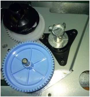
The bearing bush is an important component in a bearing product. It helps prevent abrasive wear and extends the life of the machine. Adhering to the original part specification in roundness and size of a bearing bush part through the plastic injection molding process can be a challenge. Thus, the process needs to be monitored and controlled under close scrutiny; otherwise, it may result in an unwanted sound occurring when the machine is in operation.This is due to the poor fit among each part component. Also, because of this, the production yield rates are greatly reduced. However, thekey to attainingaccurate part specification lies in balanced plastic flow during the filling stage, and the appropriate thickness design of a bearing bush. With the help of Moldex3D simulation analyses, Lite-On Technology was able to design the appropriate part thickness,pinpoint the best gate locations, and achievea tremendous success in improving product quality and yield rates.
Challenges
- Poor part roundness: Causing vibration and unwanted sound problems when a roll-bearing is in operation
- Stringent product requirements on part roundness: The roundness needs to be controlled
within 0.05 mm
Solutions
In order to find out the most optimized design and manufacturing conditions, Moldex3D simulation solution was implemented.Lite-On Technology identified the following important tasks to improve yield rates:
1. Identifying the problematic areas in the original design that may incur hot spots.
2. Changing the gate locations to get an even melt flow and effective packing efficiency.
3. Reducing deformation and warpage caused by melt imbalance and poor packing efficiency.
4. Comparing the results between the original design and the optimized designs to select the best design
for production.
5. Placing different nodes in the cylindrical region to measure roundness variation in the Z-axis
direction.
Case Study
In the original design, the thickness variation in different regions of the part could cause undesirable molding problems. The gate locations in the original design were positioned in the thin-wall area (1mm); however, the plastic melt was solidified earlier than expected when it first came in contact with the mold wall during the filling stage. Thus, it resulted in poor packing efficiency in the next stage. Another molding problem we encountered was related to the end of flow paths laid in a thick-wall region (2.2mm). In this case, we focused on the cylindrical portion of the part. Due to the thickness of the region, the heat was easily accumulated in the region and it posed a difficult task for cooling. Thus, when the part was cooled and reached room temperature, we could clearly see that the thick-wall region (the cylindrical) had a higher deformation volume (shrinkage and warpage). However, the precision of the cylindrical roundness was a make-or-break situationin terms of product quality. Therefore, the main goal in the next design change/optimization stage was to control the roundness of this region within 0.05mm.
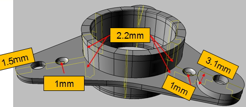
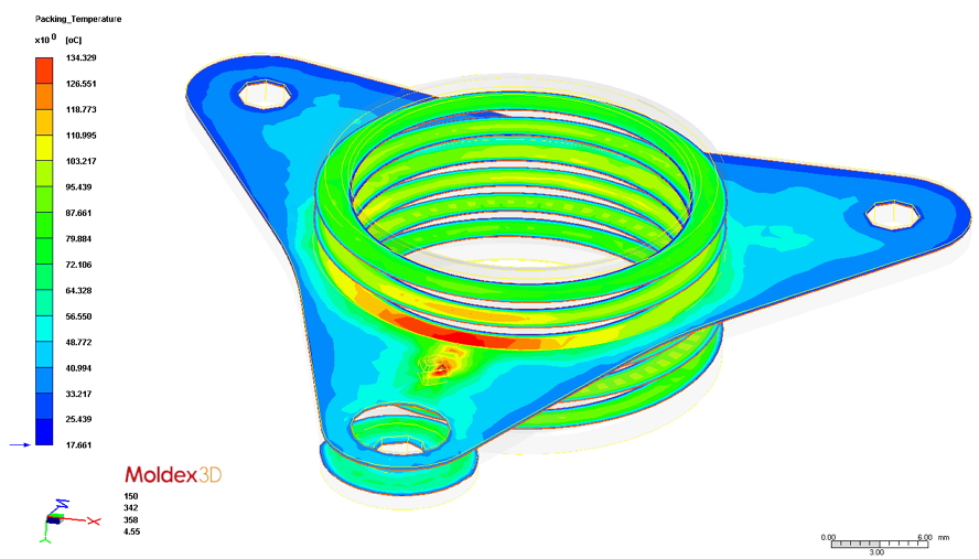
The product wall thickness variation (left) and the Moldex3D Pack analysis result (right),
which identified the shrinkage problem on the central of the cylindrical body
In order to reduce the central cylindrical body shrinkage problem, two main approaches were set for further consideration on the product design change:
1. Maintaining the original gate locations while reducing the thickness of the central cylindrical body to
decrease the deformation volume.
2. Change the gate locations to position on the circumference of the molded product to ensure effective
packing for the area.
Based on the above mentioned approaches, five different options for the design changes were simulated and validated through a real-life mold trial.
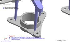
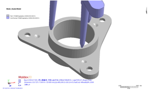
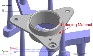
Design 2: There was no change on the original gate locations. The amount of the plastic melt traveling down to the cylindrical body was reduced to attain a more uniform shrinkage value. It made the roundness of the cylindrical region more stable.
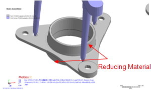
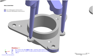
Design 4: The gate locations were positioned on the circumference of the molded product. Though it would help maintain enough pressure for the packing of the cylindrical body, the thickness of the area was not reduced so the overall shrinkage ratio was still quite high.
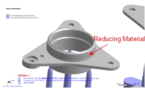
Design 6: The material was reduced from the core side to the circumference area and the gate locations were moved to the cavity side to inject the plastic melt. However, the problem of uneven shrinkage in the cylindrical area still existed.
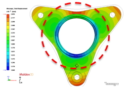
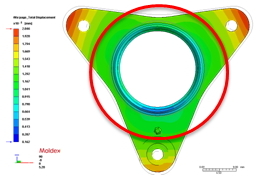
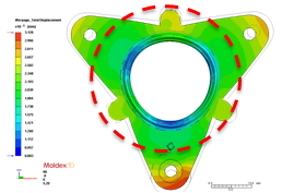
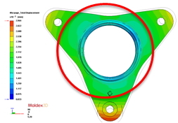
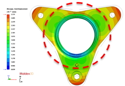
In short, via the comparison on the total displacement analysis between the original design and the optimized designs, it was concluded that Design 2 presented the best option for design change and optimization.
|
Original Design |
Design 2 |
Design 3 |
|
Three gates |
Three gates; the material was reduced |
Three gates positioned at the tabs of the molds; the circumference remained the same |
|
Design 4 |
Design 5 |
Design 6 |
|
Three gates positioned on the circumference of the molded product |
Reduced the material near the circumference with the original gate design |
Three gates with reduced material on the circumference area |
Comparison between the original design and the optimized designs
|
Original Design |
Design 2 |
Design 3 |
|
-0.106 mm~0.283 mm |
-0.016 mm~0.204 mm |
-0.08 mm~0.312 mm |
|
Three gates |
Three gates; the material was reduced |
Three gates positioned at the tabs of the molds; the circumference remained the same |
|
Design 4 |
Design 5 |
Design 6 |
|
-0.083 mm~0.296 mm |
-0.084 mm~0.273 mm |
-0.033 mm~0.281 mm |
|
Three gates positioned on the circumference of the molded product |
Reduced the material near the circumference with the original gate design |
Three gates with reduced material on the circumference area |
Comparison of Total Displacement of original design and the optimized designs
The part was revised and re-designed based on Design 2, and was measured again. A roundness of less than 0.05mm was measured which met the design specifications.
Measurement of roundness
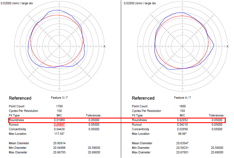 The part roundness was measured using the Coordinate Measuring Machine
Benefits
Before implementing Moldex3D, Lite-on Technology found it difficult to mass produce bush bearings due to the poor yield rates. Through the correlation study of Moldex3D simulation results with real-life molding results, Lite-on Technology has successfully increased product yieldby nearly 99%, which largely reduced the cost of mold trials and reworks, and shortened the time-to-market.
Moldex3D’s true 3D visualization makes invisible manufacturing problems visible. Through virtual prototyping and process optimization, product designers can easily incorporate design changes in the development process within a short amount of time. Moldex3D not only provides solutions for product manufacturing, but is also an asset that helps creates products with competitive advantages.
