As Ultrabooks continue to take the notebook design trend in “thin and light,” manufacturers are finding ways to keep up with the trend yet reduce production costs. Under such circumstances, the world leading component manufacturer MiTAC Precision Technology has replaced metal chassis with glass fiber reinforced plastics, which not only enables lighter and thinner body but also ensures cost-competitive in comparison to metals. However, glass fiber material might cause floating fibers and welding line problems and further lower product quality. Heat and cool process can help avoid these problems significantly, which utilizes rapid temperature-changing molding process to increase melt fluidity in the filling stage and further improve part quality within a reasonable cycle time.
There are various dynamic variotherm technologies, including Heat & Cool™, Induction Heating Molding (IHM), and Electricity Heating Mold (E-Mold)… etc. Among these advanced technologies, some increase temperature in the entire moldbase; some increase temperature only on the mold surface. But in reality, mold temperature control mechanism is extremely complex; therefore, performing and managing those variotherm technologies is very challenging in injection molding system.
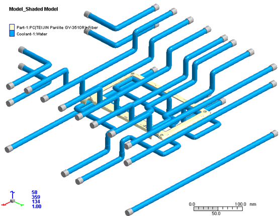
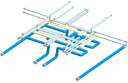
In Moldex3D, the leading plastic injection molding software, variotherm technologies can be simulated and validated with proper settings. In the following case example, Fig. 1 (a) is a CIM cooling channel design and Fig. 1(b) is the steam heating cooling channel. Fig. 2 shows the time sequence of the two different methods. In the CIM process, the water temperature is set at 80℃ at both core and cavity side. Cooling time and cycle time are 10.7 and 19.2 seconds respectively. In the heat/cool process, the water temperature is set at 80℃ at the core side. In order to reach 150℃ on the surface of cavity side, 180℃ steam is set to heat cavity side for 25 seconds in the process. Cooling time and cycle time are 25 and 58.5 seconds respectively.


Fig. 1 (a) CIM cooling channel (b) Steam heating cooling channel
CIM |
 |
Steam Heating |
 |
Fig. 2 Time sequence of (a) CIM cooling channel and (b) Steam heating cooling channel
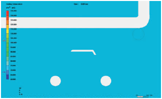
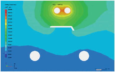
With Moldex3D’s three dimensional transient heat transfer simulation ability, temperature distribution at any specific time can be predicted. Fig. 3 shows the mold temperature cross section view at the filling stage for both cases. Also, by checking the part temperature distribution at the end of filling (EOF), we can observe the temperature increase at weld line locations (Table 1), which is helpful in improving product appearance.


Fig. 3 Mold temperature comparison between (a) CIM (b) Heat and Cool at the beginning of filling
| Methods | Weld lines temperature(℃) |
| CIM | 170-200 |
| Heat and Cool | 190-220 |
Table 1 Weld lines temperature range at EOF
Moldex3D provides an effective way for fast design validations. By predicting transient temperature distribution in three dimensional, users can predict the effects of variotherm technology and avoid potential problems prior to mold making stage. We also would like to share a conference paper, The Effects of Various Variotherm Processes and Their Mechanisms on Injection Molding, which conducted various technologies, including Conventional Injection Molding (CIM), Heat & Cool™, IHM, and Emold by using true 3D transient cool technology.
For performing variotherm analysis in Moldex3D software, please continue reading our Tips and Tricks.