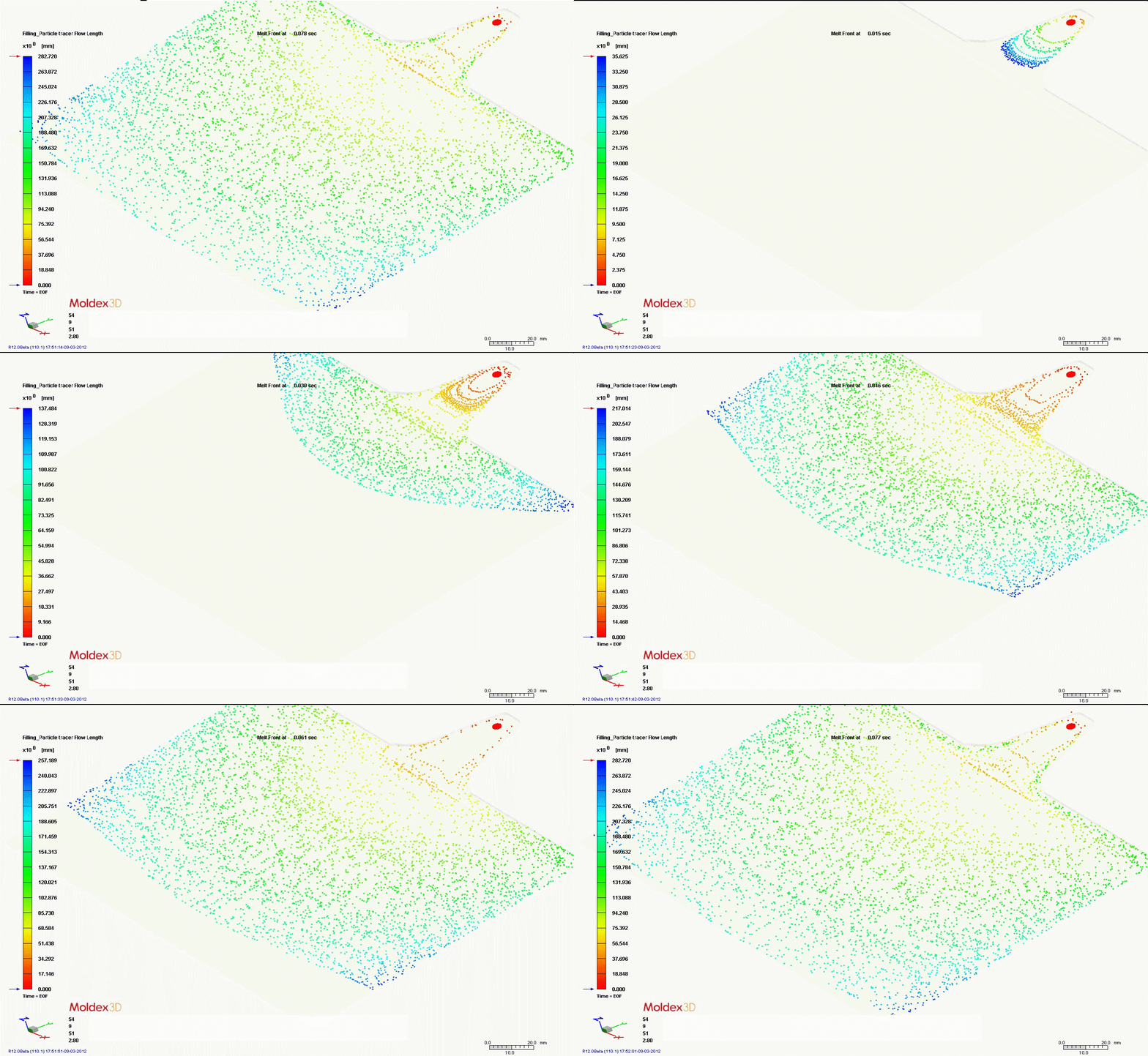
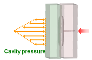
Injection-compression molding (ICM) is widely used in manufacturing of precision optical lens, reflector, and storage media. The ICM process utilizes a controlled variation of cavity spacing during injection. The major difference between ICM and conventional injection molding (CIM) is the applied pressure profile when the melt is distributed to fill the cavity. Fig. 1 shows that for the CIM process, the pressure driving the melt needs to transfer all the way from the sprue to the flow front, leaving a high pressure region at the center and low pressure around the rim. Molding defects/difficulties such as warpage, high residual stress and high filling pressure are often the results from this uneven pressure profile. By comparison, the ICM process in Figure 2 represents a more uniform pressure distribution and has the least difference. The filling pressure and the resulting residual stress are thus lowered.
 |
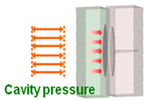 |
Fig. 1 Conventional injection molding process shows pressure gradient |
Fig. 2 Injection compression molding process shows a uniform pressure distribution |
Residual stress in optical and thin-walled products can be overcome with ICM process now. Figure 3 shows a comparison of stress of the light guide plate example. Compression apparently reduces the stress from 48 MPa to 12 MPa. The other advantages using ICM include less warpage, shorter cycle time, lower required clamping force and better venting to improve product quality.
 |
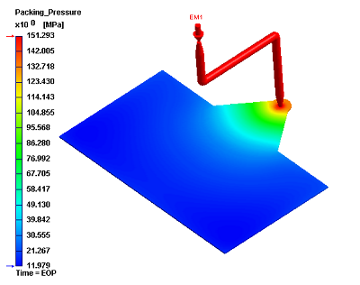 |
Fig. 3 Pressure applied to the examplary light guide plate product shows a largely reduced pressure value acted on the cavity between conventional injection molding (left) and injection compression (right)
Despite its many advantages, setting up a successful ICM process is difficult due to the complexity controlling injection/compression timing sequence and mold movement. Process engineers tended to adopt trial-and-error method as a result of the constraints mentioned above. Usually gap size and mold movement must be fixed first to obtain the desired injection rate profile. To optimize the entire process is time-consuming; for example, finding a set of initial condition without causing flash and short shot sometimes takes days to complete. Free programmability turns setting up ICM a daunting task.
Moldex3D provides complete solutions to conduct virtual molding trials with features including:
- Dynamic computation with simultaneous or sequential movement of independent mold components and injection unit.
- Complete settings of injection and compression speed profiles or pressure controls; injection on/off switch.
- Informative post processing displays such as residual stress, packing pressure, cooling temperature for process optimization guidance.
- Fiber materials orientation analysis may be included for realistic shrinkage and flatness prediction.
- Valuable machine related information such as sprue pressure and clamping force.
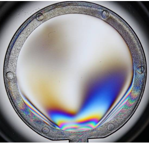
For optical product manufacturers, Moldex3D provides the Optics module, which is a unique birefringence pattern simulation tool based on its viscoelastic material property. Lens maker can now optimize their process setting to reduce the residual stress by observing the estimated birefringence pattern with a certain incident light direction and wavelength. Figure 4 shows the consistency between the actual product and Moldex3D simulation results. The optical product manufacturer can find complete molding simulation solutions in Moldex3D. This speedy virtual molding trial from Moldex3D can definitely help you get the most out of the injection compression process.
 |
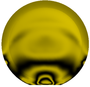 |
Fig. 4 The birefringence pattern of a molded optical lense product (left)
|
|
Related articles:
- A Novel Approach for Predicting Birefringence of Optical Parts
- Simulation and Verification of True 3D Optical Parts by Injection Molding Process