 |
Ben Lai, Engineer at Technical Support Team, Moldex3D |
In the molding analysis, the simulation inside the barrel will affect the melt conditions when it enters the cavity, and further impact the whole injection molding process simulation. To better describe the melt behaviors such as compression inside the barrel, it is necessary to have good model construction of the injection units. The injection units, including nozzles and screws, can have complicated and diverse designs, so how to achieve both high-quality modeling and development efficiency is a critical issue.
To eliminate the gap between simulation and on-site conditions and improve the accuracy injection pressure prediction, Moldex3D has included the dynamic simulation at the filling and packing stages inside the barrel. Moreover, Moldex3D 2021 further provides the Nozzle Zone Wizard feature for users to easily create a true nozzle type, making analysis more accurate and reducing the loading in pre-processing.
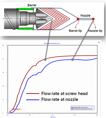
Flow rate changes caused by the screw compression
The Operation Processes
Limitation
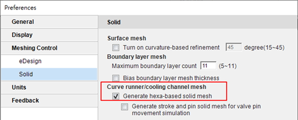
- Make sure the Generate hexa-base solid mesh is enabled in the Solid tab under Preferences.
- The 3D barrel compression model only currently supports the machine mode and standard cool analysis of the injection molding process.
Step 1:Model Preparation
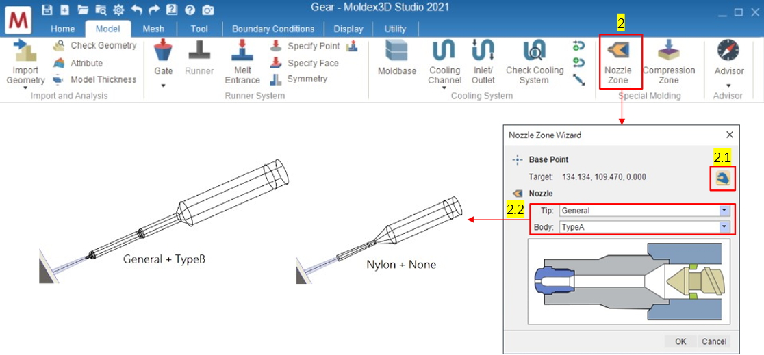
- Prepare the required components of the model for analysis. Then, click Nozzle Zone in the Model tab to activate the wizard tool for 3D barrel modeling.
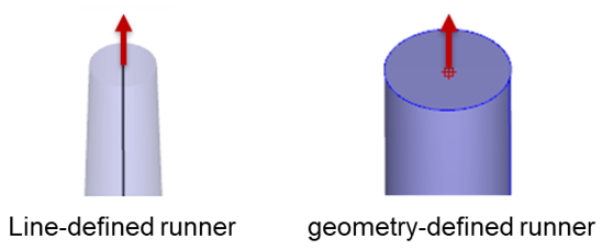
- For the Base Point, select the line-defined runner’s endpoint or the geometry-defined runner’s circle center.
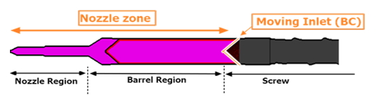
- For the Nozzle Tip and Body, Nozzle Zone Wizard provides 3 types of tips and bodies. 9 combinations of barrel shapes in total are provided (users can preview in window below).
Note:
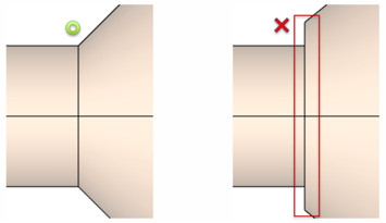
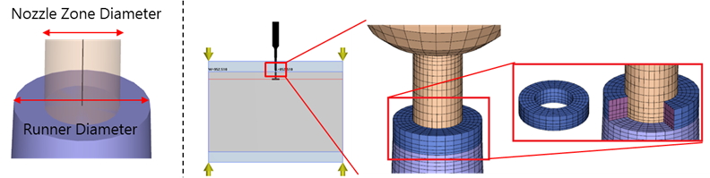
(1) If users want to edit the nozzle zone type after the setting, remove the nozzle zone model and reset with the wizard again. If users just want to modify the nozzle zone dimension, make sure it is continuous at the junctions of each segment. The cross-sectional dimensions of the runner should be larger than the Nozzle Zone.
(2) When a nozzle zone is connected to the runner, the default moldbase is attached to the junction of the nozzle zone and the runner. A nozzle type’s ring-shaped solid mesh will then be automatically generated (the models with mold base and mold plates components are both supported).
Step 2:Analysis Settings
- Finish all model preparations and mesh generation, and then launch the Final Check.
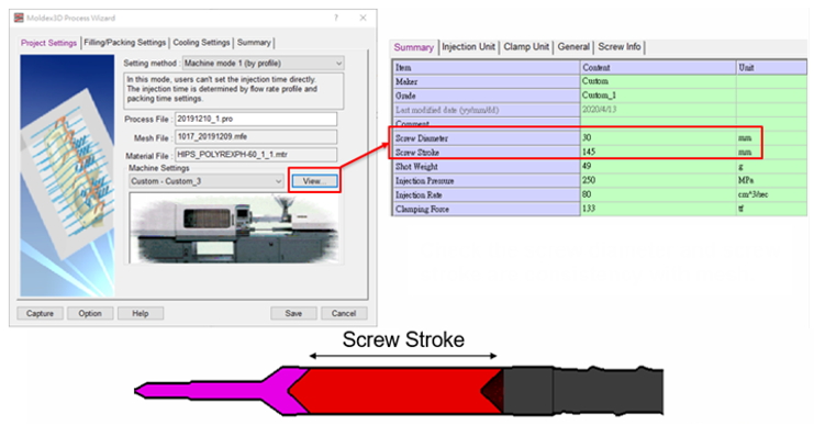
- Studio will take Machine mode as default because of the nozzle zone in the model. Then, enter the machine information in the machine parameter column of the project settings. Make sure the machine’s screw diameter and screw stroke fit to the nozzle zone setting in the previous step.
- Finish all analysis settings and submit the run for calculation.
Step 3: result interpretation
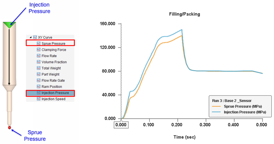
- Moldex3D will simulate the plastics compression behaviors at the screw front and nozzle end during filling and packing processes.
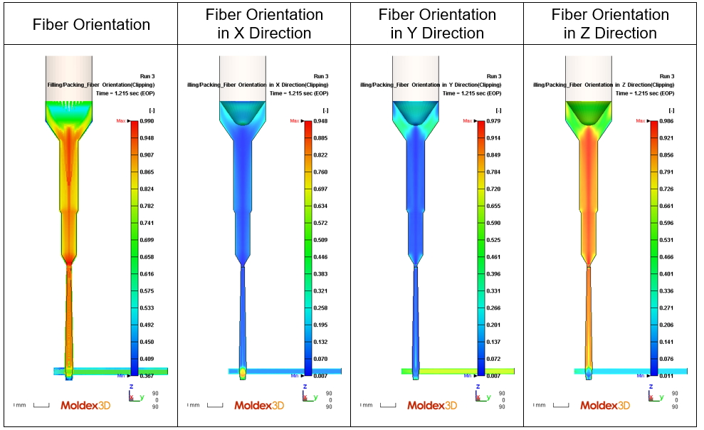
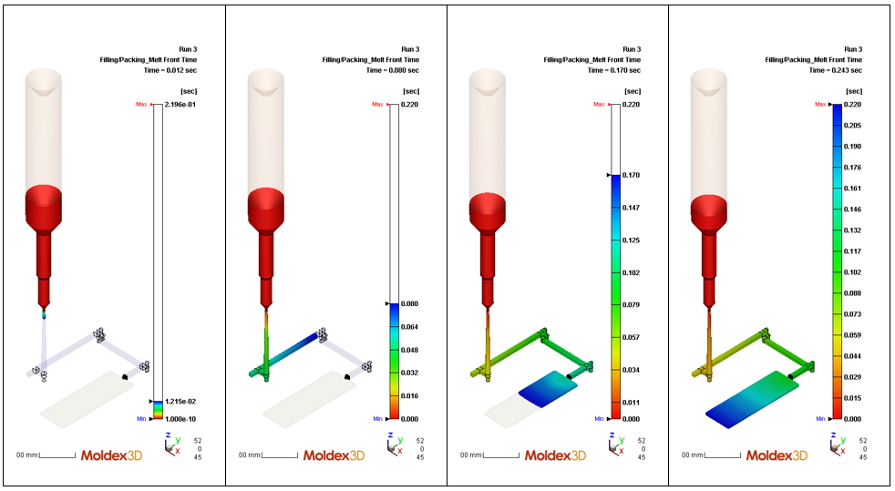
- The melt front time, particle tracking, and fiber orientation results can be shown in the nozzle zone.
Melt Front Time
Particle Tracking

Fiber Orientation (Clipping)