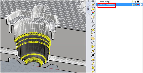
Moldex3D Mesh tool has a new function called “Auto Set Heat Conduction B.C.”, which helps to automatically detect heat conduction surfaces. In hot runner system, there is insulated air gap between hot runner metal components and mold plates. The insulated air gap can prevent heat loss from hot runner metal, and therefore keep high temperature. There will be no heat transfer between hot runner metal and mold plates except heat conduction faces.
But hot runner metal still needs some features to hold and fix inside the mold plate. Thus the contact surfaces between hot runner metal and mold plate will cause heat transfer. Defining heat conduction surfaces can simulate the heat loss from contact surfaces and get more precise simulations results.
In CAE simulation, users usually have to manually identify and specify the heat conduction faces (shown in red lines). Moldex3D Mesh can automatically extract those surfaces.
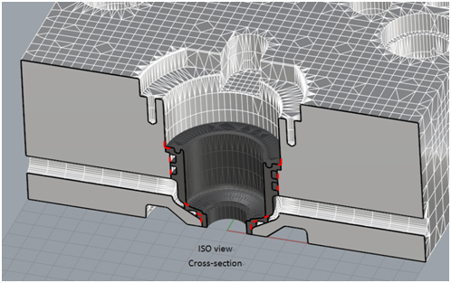
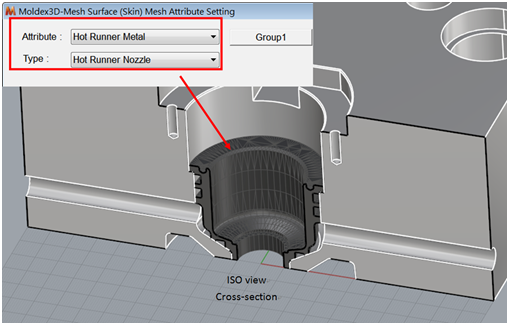
Step 1. Convert hot runner metal into a closed mesh and set attribute of hot runner metal.
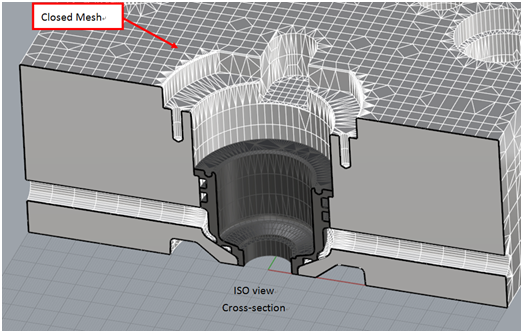
Step 2. Convert mold plate into a closed mesh.
Step 3. Click the button ![]()
![]() inMoldex3D Mesh tool, then select the mesh of mold plate.
inMoldex3D Mesh tool, then select the mesh of mold plate.
It will automatically search contact surface and create a new layer named “Heat Conduction.”
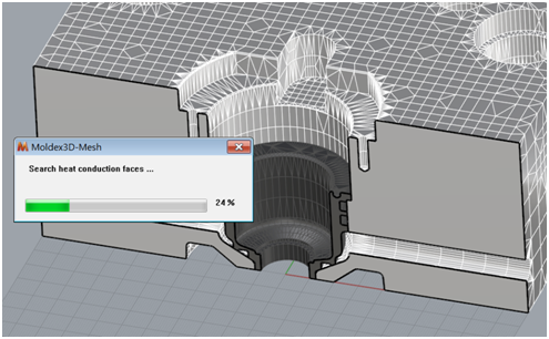
Result
A new layer named “Heat Conduction.” Users can simply select those surface meshes and define the attribute as “B.C. – Heat Conduction Faces.”
