Jasmine Ho, Staff Engineer at Technical Support Division of CoreTech System
Moldex3D Studio provides users with convenient functions related to mesh editing, which can customize mesh distribution. Users can create meshes automatically with the Moldex3D default parameters, which can greatly reduce the time for meshing a variety of models. However, in certain cases, various tools are also provided for users to edit mesh to further optimize mesh quality, making the modeling process more user-friendly.
The new functions of Moldex3D allow users to set seeding more conveniently, auto copy/paste of mesh contact surfaces, adjust the maximum and minimum size and gradient of the mesh and turn on curvature-based refinement, allowing users to no longer be limited by the default parameters.
The following introduces how to apply the Auto Copy/Paste function for matching mesh on contact surfaces. This function helps users to easily develop fully matching contact surface mesh, ensuring continuity of analysis results and avoiding analysis errors by non-matching mesh in specific scenarios.
Step 1. Import Geometry
Import the part and part insert in Studio, and the contact between the two can be seen in Figure 1.
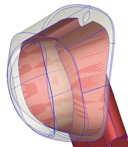
Figure 1 – Contact surface between part and part insert
Step 2. Seeding – Consistent seeding of contact surfaces
Click Seeding and specify global and local mesh size. For local seeding, select the boundary of the contact surface, such as the yellow edges in Figure 2, and give the Uniform seeding to ensure consistent seeding between part and part insert. This step is intended to reduce the effort of processing after applying the automatic copy/paste function.
Note: Box selection by cursor can be used to select overlapping edges between the part and part insert at the same time. making the whole operation more efficiently.
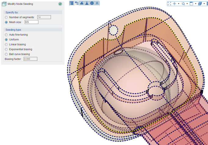
Figure 2 – Consistent seeding of contact surfaces
Step 3. Generate Surface Mesh
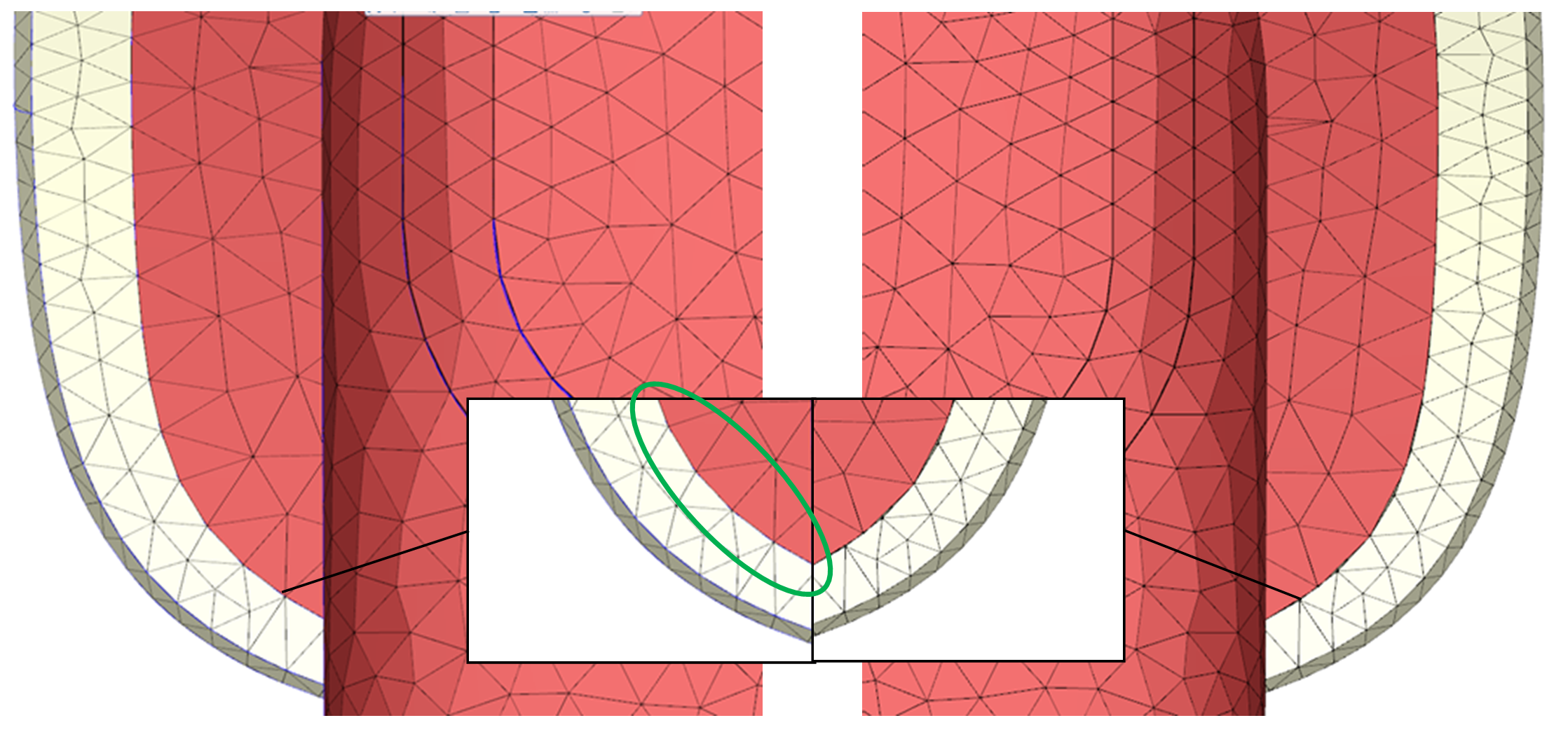
Click Generate to construct meshes and pin select Surface Mesh. After the surface mesh is completed, there are many non-matching surface meshes on the contact surface between the two objects, as shown in Figure 3.
Users can show the seeding information (Figure 4) in Mesh–Show Seeding to confirm that the surface mesh generated is the same as the seeding location of Step2.
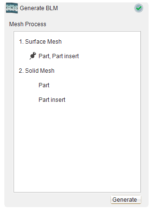
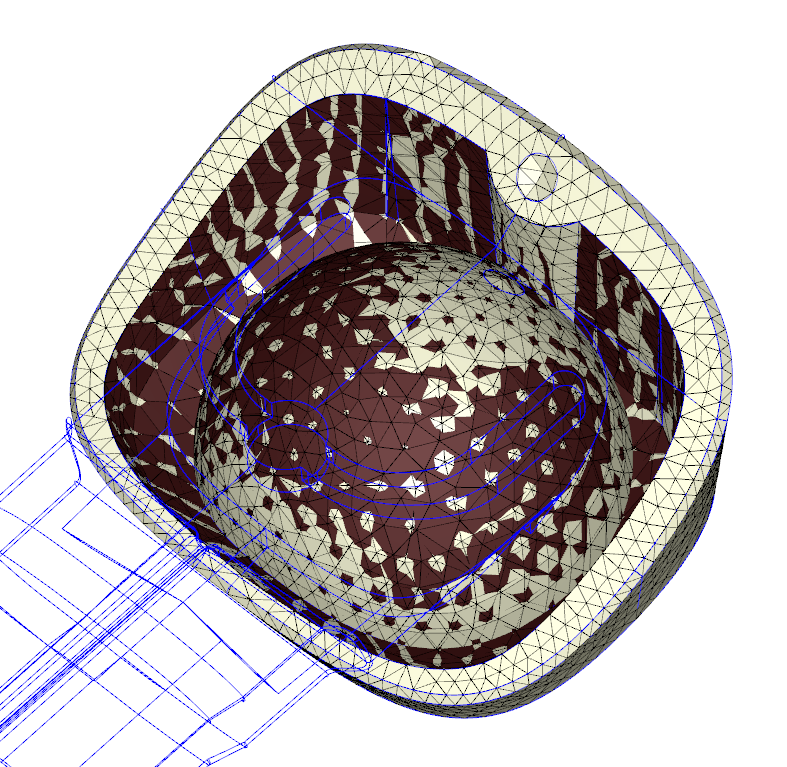
Figure 3 – Inconsistent surface mesh on contact face
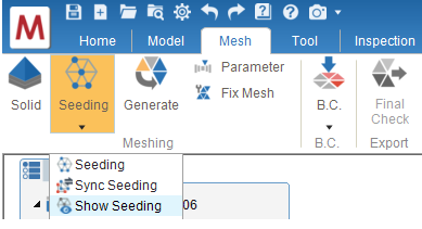
Figure 4 – Show Seeding
Step 4. Auto Copy/Paste
In Fix Mesh, Click Auto Copy/Paste (Figure 5). Apply the contact surface mesh on the part side to the insert. First, select Part as the reference object and select Part Insert as the target object. Then, the meshes of the contact surfaces between two sides are matching after the function is applied.
Matching surface meshes and non-matching meshes will be marked in blue and red (Figure 6), for users to double-check, if Solid – Allow non-matching faces is not checked in Preferences – Mesh.
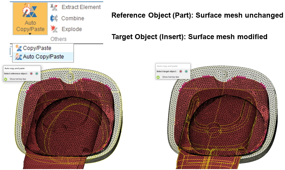
Figure 5 – Auto Copy/Paste
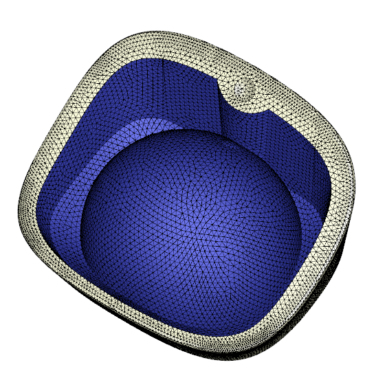
Figure 6 – Fully matching surface mesh after Auto Copy/Paste with minimized mesh fixing effort
Step 5.Fix Mesh
After Auto Copy/Paste, sometimes the boundary of fixed mesh will cause a small amount of other errors, which need to be repaired manually (Figure 7). The repair steps are as follows:
- Launch Merge Nodes and select all surface meshes, uncheck ‘Only merge nodes on free edges’, and click OK. Then, most of the free edges will be repaired after merging nodes.
- Remove the inner shell caused by the automatic copy/paste by clicking the inner shell in the defect list to select them and directly pressing Delete on the keyboard.
- The remaining mesh defects can be repaired through general surface mesh repair methods. In this example, the remaining free edges can be repaired through Stitch.
Note: For how to make good use of Moldex3D mesh repair tools, please refer to Moldex3D Help.
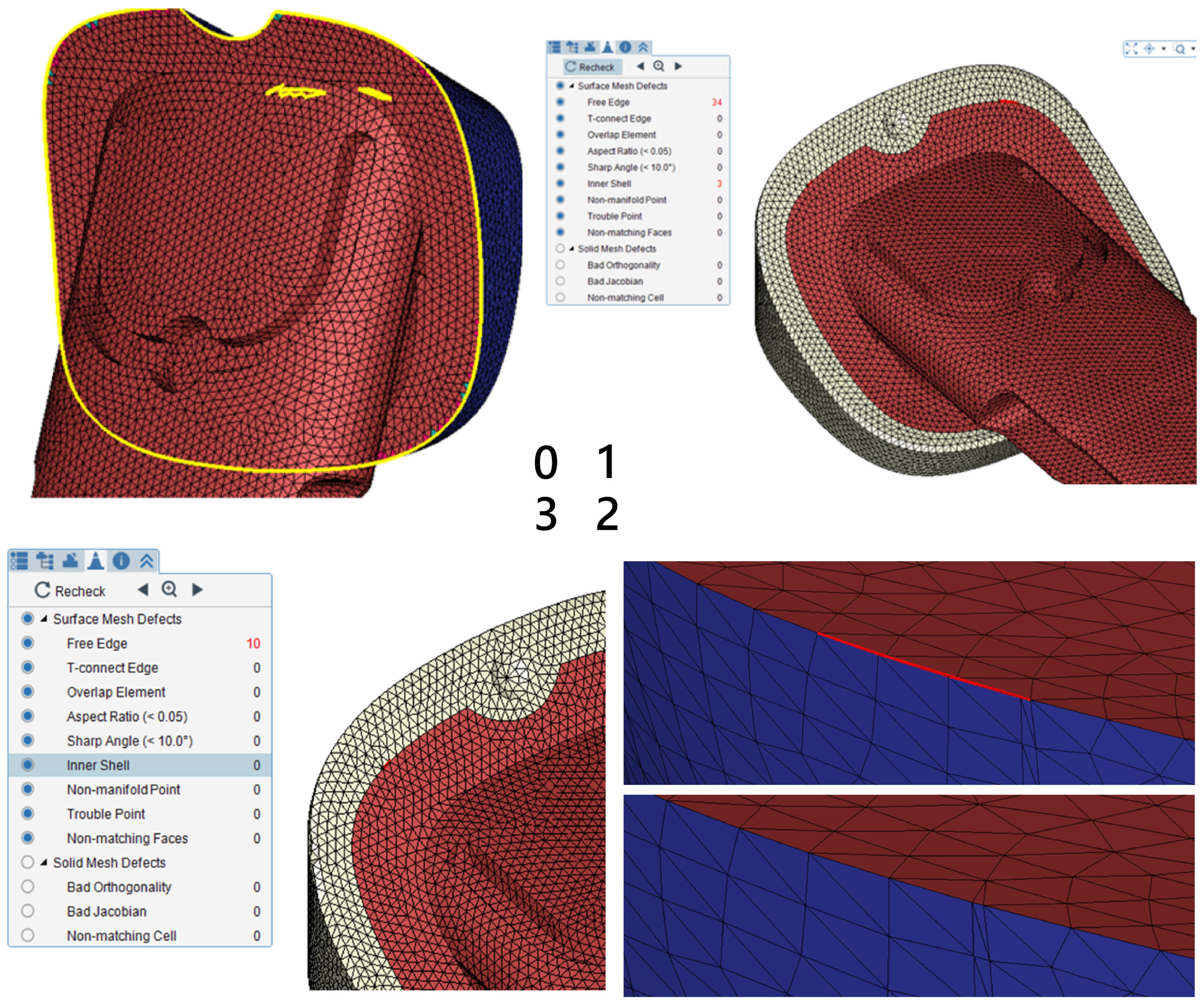
Figure 7 – Fix surface mesh defects:
1) Merge Nodes; 2) Remove inner shell; 3) Fix other defects
Step 6. Generate Solid Mesh
After the above procedures, a completely consistent contact surface mesh is constructed, and user can proceed to the next step, pressing Generate to create the solid mesh. Compare the mesh that was generated from the Auto Copy/Paste function and what was generated by using default parameters. After Auto Copy/Paste, the mesh nodes on the contact surface are all connected between part and part insert, while the original surface mesh by default will result in non-matching mesh, as shown in Figure 8.