
 |
Jasmine Ho, Engineer at Technical Support Team, Moldex3D |
Plastic chip encapsulation is a molding process where chips are capsulated with epoxy molding compound (EMC) to prevent physical damage or corrosion. We should consider the interconnection between microchips and other electronics (i.e., wire bonding), curing phenomenon of thermoset material, and various control management of process conditions.
Moldex3D Studio now supports IC transfer molding and helps mold designers to analyze the chip encapsulation process from filling, curing, to cooling. Significant molding problems can be predicted and solved upfront, helping engineers enhance chip quality and prevent potential defects more efficiently. The simulation results would also help in design optimization as well as cost reduction.
Operating Procedures
Limitation
- A melt entrance is required in the model.
- Users had to rely on Rhino to generate meshes, but now they can also do it in the Studio. (Note: depending on the complexity of the model and the required tools, users might still need Rhino or other software to generate meshes.)
Step 1: Model Preparation
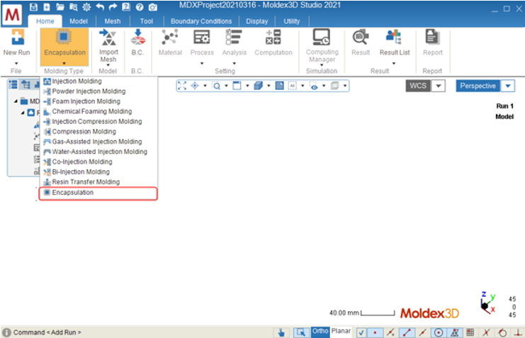
- Create a new run in Moldex3D Studio and select “Encapsulation” in the “Molding Type.”
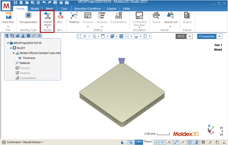
- Prepare a model for simulation and click on “Final Check” to complete mesh generation. Users can also import a finished mesh file (MFE) by clicking on “Import Mesh.”
Step 2: Material and Process Settings
Define material for each component in the “Material Tree,” then click on “New” in the drop-down list in “Process” to enable Process Wizard for settings: (1) Choose “Transfer Molding” in “Analysis type.” (2) Finish setting up the process condition.
![]()
![]()
Step 3: Analysis Settings
For “Analysis Sequence,” select “Transfer Molding Analysis 2 – F C W.” (Users can also customize the analysis sequence by selecting “Customize.”)
Note: Projects can be submitted directly if no modifications are required, and users can also set up wire sweep analysis and paddle shift analysis in the “Encapsulation” tab.
![]()
![]()
Step 4: Submit Projects
After setting up the pre-processing, click on “Run” to start the analysis. Moldex3D will then call the Computing Manager for users to check the calculation progress and details.
Note: Users can also click on “Computing Manager” to launch Computing Manager and adjust settings for parallel and remote computing before submitting projects.
![]()
Step 5: Results Checking and Report Exportation
Results will be shown in “Result” in the project tree when the analysis is done. Click on “Result” to switch from “Home” to “Result” tab. In “Result” tab, users can use different post-processing tools to view customized or advanced results.
![]()
Users can use the “Report Wizard” in the Studio to automatically generate reports. Click on “Report” in “Home” tab to open the “Report Wizard.” Set the content format before exporting the report. In the “Preference” section, users can customize the format, image, and video in each report. Key in the report name and location and click on “Start” to start to generate the report.
![]()
![]()