Cindy Teng, Engineer at Technical Support Division of CoreTech System (Moldex3D)
With the development of CAE simulation techniques, producers can find problems to modify product design in a more scientific way throughout the manufacturing process. Meanwhile, structural analysis plays an important role to determine the robustness of a product. The common method to do structural simulation is to use the product design model with one or more isotropic materials. However, it will ignore the influence of molding process on the product and the anisotropic material properties, especially when using fiber reinforced materials.
Through the Moldex3D FEA interface, the molding analysis result from Moldex3D can be integrated into the structure analysis. With the consideration of manufacturing effects on the material and the product, such as the material properties, temperature, pressure, residual stress and even deformation, the structural analysis result can then be more realistic.
Step 1
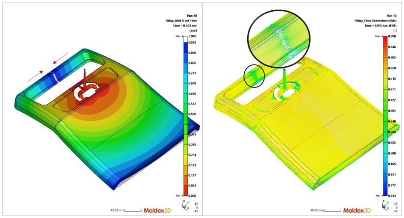
Use fiber-reinforced material to complete an analysis with fiber orientation predictions in Moldex3D Studio. In this project, the Melt Front Time result shows that two different melt fronts join together at the top of the product. The filling pattern affects the Fiber Orientation (Skin), causing the fibers to align in the Z-direction in the middle, where the flow front meets, and in the Y-direction on both sides. Generally, this will result in structure strength reduction in this area due to the anisotropic property of fiber filled material.
Step 2
Switch to FEA Interface ribbon and click FEA Interface to open the wizard.
Specify the Stress solver and Output mesh. This document demonstrates how to export fiber material properties and the effect of weld lines on material strength to ANSYS via mapped mesh.
Select Output mesh as Mapped and import the additional mesh file prepared in the structural analysis program. The molding analysis results will be mapped to the imported mesh from the original Moldex3D mesh.
Note: The mapped mesh should be generated by structural analysis software before using FEA interface. Without an additional mesh, the Original mesh in Studio can be used to carry the molding analysis results. However, one should consider if the Original mesh is applicable in structural analysis, such as the amount of elements and the mesh structure.
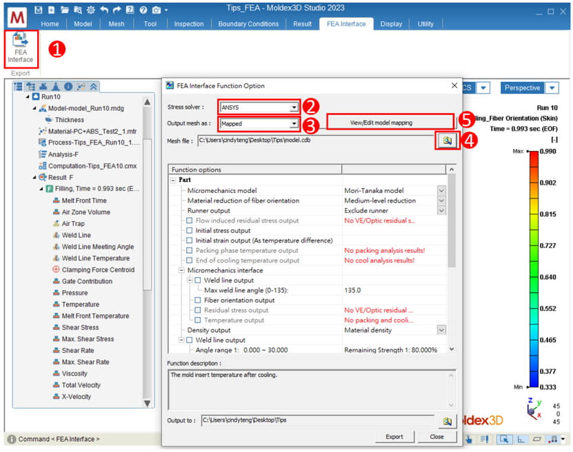
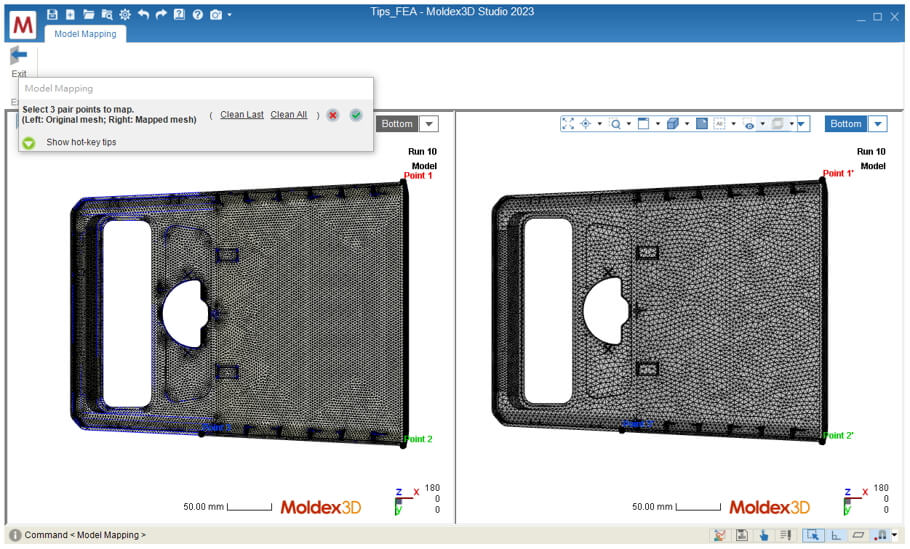
Click View/Edit model mapping to confirm the position of the Studio mesh and the Mapped mesh. If the coordinates of these two models are inconsistent, Auto Move or 3-points mapping can adjust the position and orientation of the model. Choose 3-points mapping in this case, select 3 guide points both on Original and Mapped model, and click OK to apply mapping.
Step 3
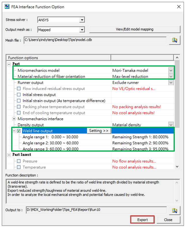
Select in Function option. The anisotropic material properties of fiber filled materials and the strength reduction caused by weld line will be exported in this demonstration, showing the structural analysis result under the influence of property variation induced by filling pattern in different product areas. With fiber-reinforced material used, select Micromechanics model [Mori-Tanaka] and level of Material reduction of fiber orientation [Max-Level].
Then, enable Weld line output to consider the strength reduction corresponding to different weld line meeting angles. Based on the actual experimental results, set the relation between the weld line Angle range and the material Remaining Strength as shown below. Export the file after selecting the stress solver, output mesh and the function options.
Note:
- The mesh with material properties will be exported with or without selecting any Function options.
- If the analysis result does not exist for a function, the corresponding option will be shown in red. For example, this demonstration only includes a filling analysis, and thus the packing and cooling results output are marked in red.
- Select the material reduction level at Material reduction of fiber orientation. Max-level reduction indicates that the amount of material groups will be significantly reduced which is beneficial for saving the calculation time. However, oversimplified material data may impact the accuracy of fiber orientation result. On the other hand, No reduction can completely export the details of fiber orientation using massive amount of material groups, but increasing the calculation time or possibly exceeding the limitation of structural analysis software.
- The options under the Micromechanics interface are exported to the nonlinear multi-scale material modeling software and cannot be directly used in the structural analysis software.
Step 4
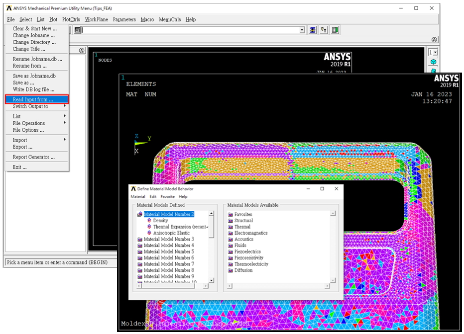
Switch to structural analysis software (ANSYS in this example) and import the mesh file. The input of anisotropic material properties when considering fiber orientation effect can be checked by material numbers and material model. Apply fixed and displacement constraints and calculate the Von Mises Stress.
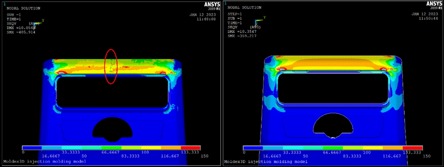
Step 5
The left figure below shows the result of using Moldex3D FEA Interface to export the material properties when considering the fiber orientation. The elastic modulus is lower in the middle of the upper part of the product due to the influence of fiber orientation on the weld line. The structural analysis result then shows that the higher stress in that region. In the right figure, if molding simulation is not considered, then the stress distribution at the upper part of the product is more uniform. The difference in these results indicates that the structural analysis results may be misleading if the molding simulation is not considered.