This article is for Shell simulation users who have large models and need fast analysis. Through the Shell modeling technique, the calculation time and analysis resources can be largely reduced. For 2.5D objects, the differences between using Shell and Solid are the pre-processing and calculation time. The advantage of Shell modeling is significant calculation speed-up due to its lower element counts and thus enables a quick validation of design and process changes.
Moldex3D provides Shell users with a more convenient pre-processing tools and a complete set of Shell mode analysis workflow in Studio, so that users can do mesh pre-processing and analysis settings with the same one-stop experience as the other Solid mode modules. In addition, Moldex3D also supports Shell with remote computation on Linux and DOE optimization functions, which greatly reducing the calculation time and allows users to obtain optimal design solutions more quickly. The following will introduce how to build a Shell model in Studio and tips.
Step 1: Create a New Run
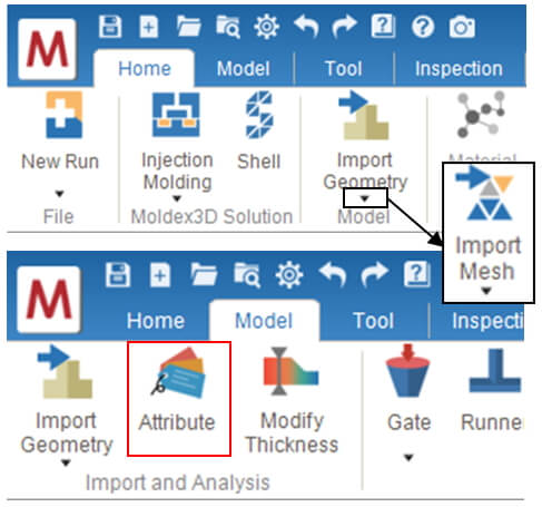
Create a new project and click Molding Type to select Injection Molding and use Mesh Type to choose Shell. Import Mesh to import a completed mesh model that mostly is ready for simulation job.
To prepare Shell Model in Studio, click Import Geometry to import surface mesh (e.g., STL) for part and other components such as runner and melt entrance (or using functions in Tool Tab to create layout manually), and then assign them with attribute to continue.
Note: The most significant difference between Shell and Solid is the pre-processing workflow, and Model Tab and Mesh Tab in Solid mode are merged in Model Tab in Shell mode
- The Molding Type only supports Injection Molding.
- The geometry type supports IGS, STL and NAS.
- Mesh type supports MSH.
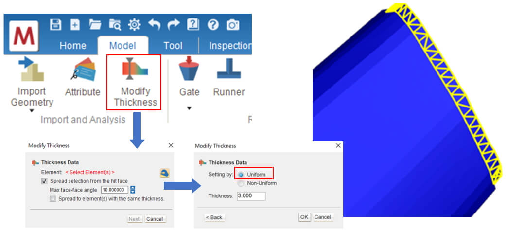
Step 2: Modify Part Thickness
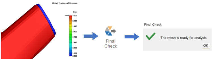
Switch to the Model Tab and Click Modify Thickness, select target surface element to set thickness and press Enter to confirm selection. Select Uniform and modify the thickness, click OK to complete the same thickness modification, and display the modified thickness distribution.
After completing the setting, click Final Check on the Model Tab to check the model setting.
Note: If users want to set the non-uniform thickness, users need to select Non-Uniform to modify the related nodes.
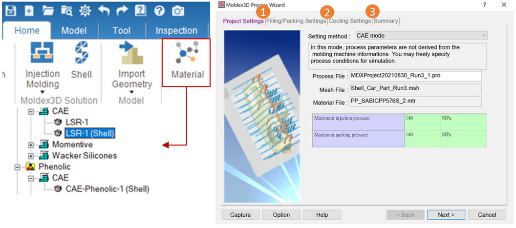
Step 3: Set Material and Process Condition
Switch to the Home Tab, click the Material Wizard to select the material. If users want to use a thermosetting material, please select the item marked with Shell (see image below). Click Process Wizard to set the Process Condition, Project → Filling/Packing Setting → Cooling Setting, and after the parameter setting is completed, click Finish to complete the setting.
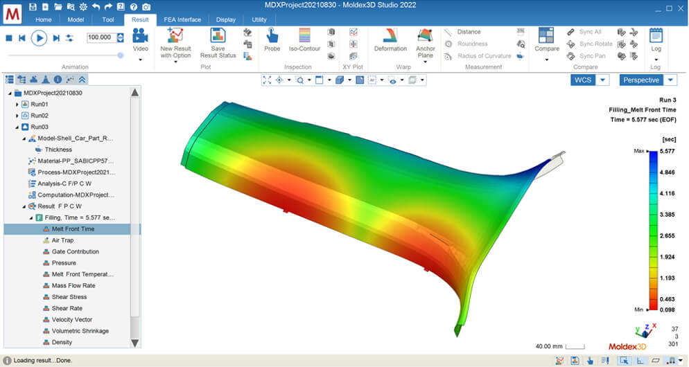
Step 4: Analysis Results
Click Analysis, select the sequences to be analyzed, and click Run to submit the analysis. After completing the analysis, select the tree directory to view the Shell project results, and then users can use the tool in the Result tab to observe the analysis results.
Notes:
- If users have other calculation requirements, they can click the Computation to modify.
- Shell Module supports Linux analysis to speed up operation time.