 |
Pierre Yeh, Engineer at Technical Support Team, Moldex3D |
To compare injection molding and simulation results, the most critical procedure is to make the input data in the simulation consistent with the real molding conditions, in which the machine movement modeling is the most important issue. In the traditional simulation, the screw movement is simply transferred into the speed and pressure imposed on the melt, which has oversimplified the real melt flow behaviors. It does not fully consider the high temperature and obvious changes in compressibility (including viscosity and PvT) inside the screw. Therefore, if the screw’s dynamic motions inside the barrel can be included in the filling and packing simulation, we can obtain better dynamic behaviors simulation of the melt and a more accurate injection pressure prediction. The following steps show how to include the screw compression effects in Moldex3D simulations.
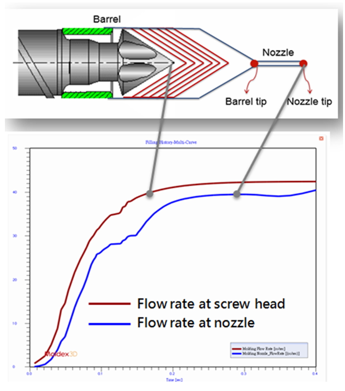
The flow rate changes caused by the barrel compression
Operating Procedures
Limitation
Pre-processing:
1. In Moldex3D 2020, only Moldex3D Mesh can be used to generate 3D barrel mesh in Rhino. (Moldex3D Studio 2021 will support the Nozzle Zone Wizard.)
2. It is recommended to generate Hexa mesh for the nozzle zone.
3. Only matching mesh is supported.
4. The cooling analysis only supports Solid cool.
Project:
1. Moldex3D Studio only supports setting and analysis in (incomplete sentence).
2. Only Injection Molding and Machine Mode are supported.
3. The simulation of the 3D Barrel Compression does not support displaying the results of the cooling analysis yet.
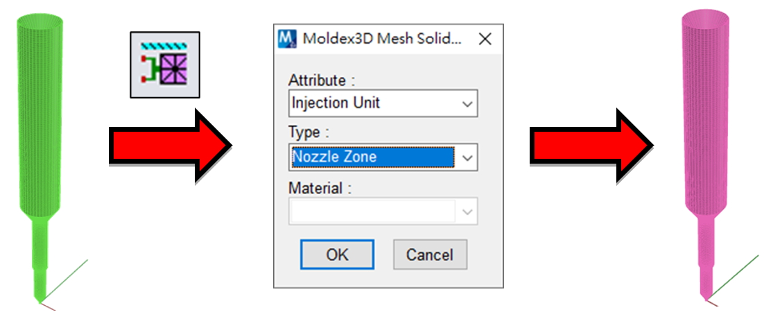
Step 1:Moldex3D Mesh attribute setting
The following attributes are the basic requirements for 3D Barrel Compression.
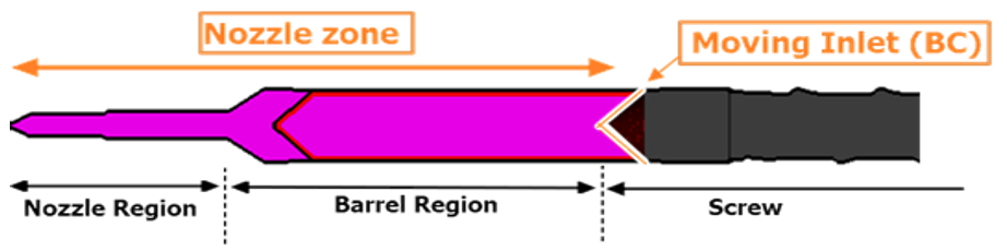
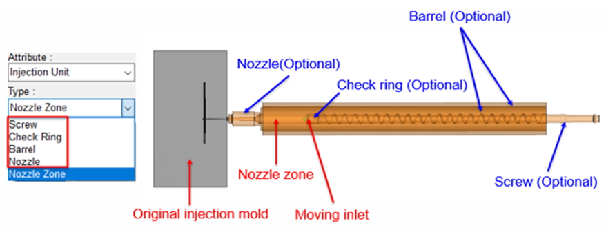
1. “Nozzle Zone” Solid Mesh
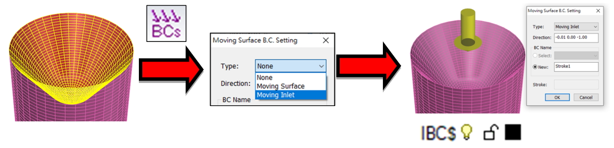
2. “Moving Inlet” Surface Mesh
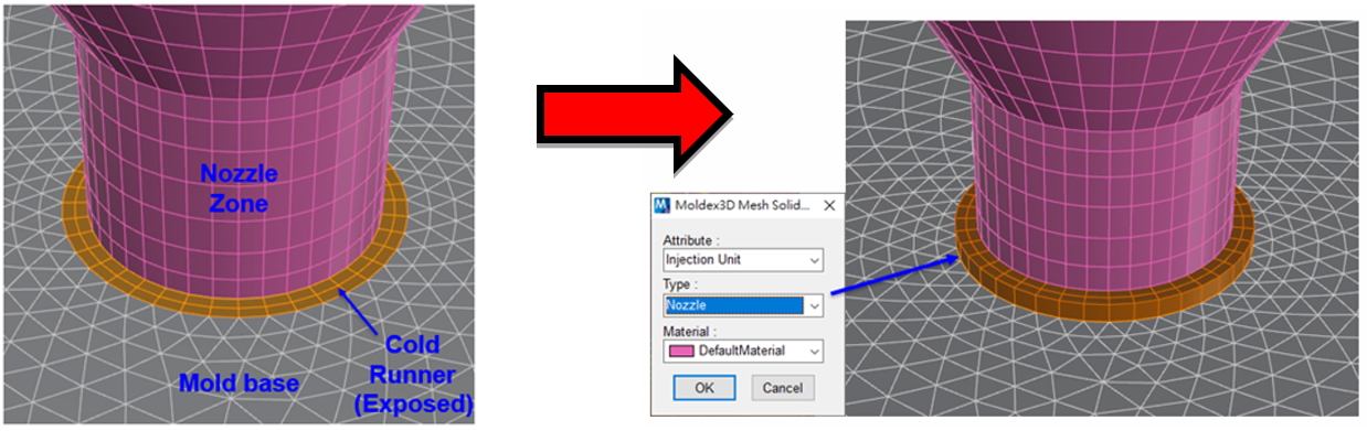
3. “Nozzle” Solid Mesh (to cover the exposed area.)
The following attributes can be established according to users’ requirements.
- Screw
- Check Ring
- Nozzle (The entire model)
- Barrel
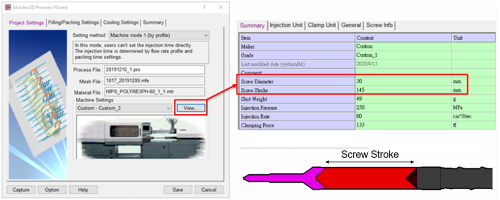
Step 2: Project settings
Prepare an Injection Molding project in Studio with the machine information specified in the machine interface of Process Wizard.
Finish all other analysis settings for the Injection Molding process simulation and submit them for calculation.
Step 3: Results
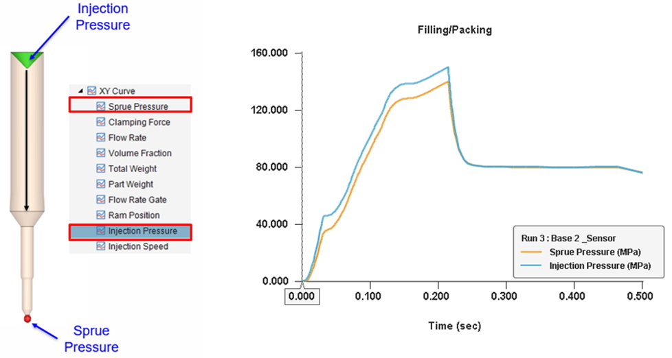
Moldex3D can simulate the compression behaviors of the plastic at the screw tip and the sprue during the filling and packing processes.
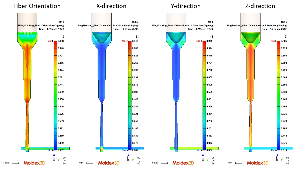
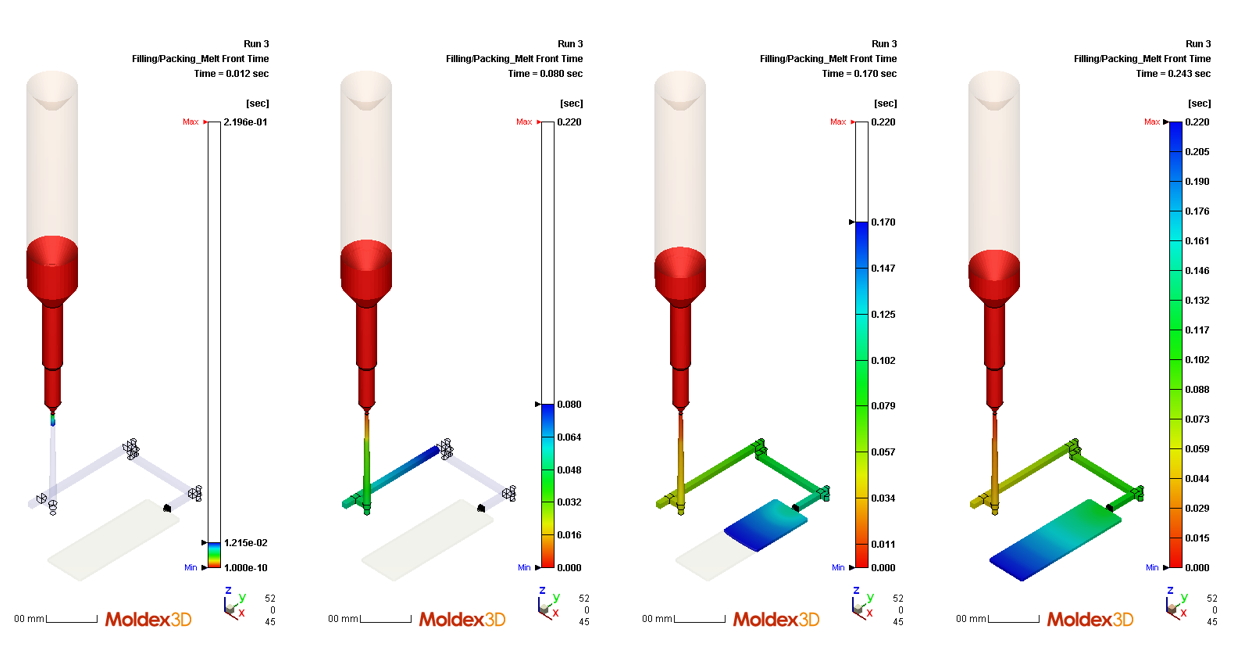
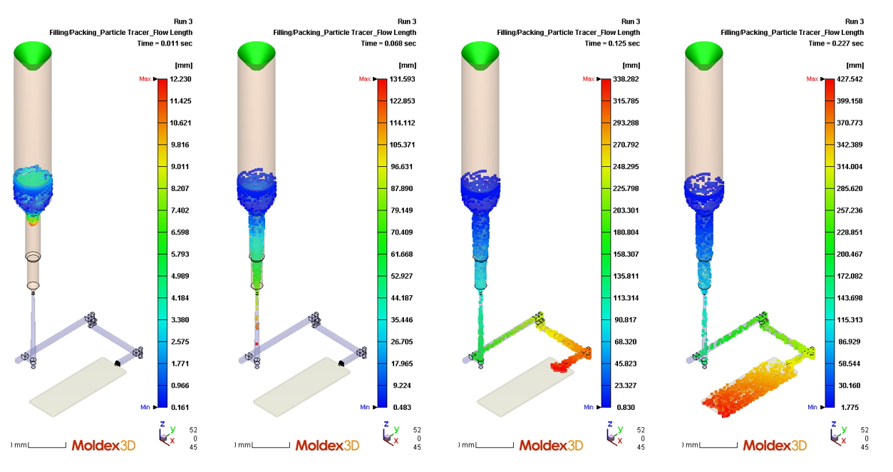
The melt front time, particle tracer, and fiber orientation results can be shown in the barrel.
Melt Front Time
Particle Tracer
Fiber Orientation (Cross-section)