| Millie Lin, Engineer at Technical Support Team, Moldex3D |
In the model development for IC packaging simulation, it is normally time-consuming to build up mesh manually, let alone the meshing of complicated models. Moldex3D Studio provides the auto meshing technology aiming at automatic solid meshing based on the 2D layout and primary settings. The advantages of this technology are to save time on pre-processing and enhance the user-friendliness for IC modeling.
For the Auto Hybrid Mesh, users should prepare a 2D layout design with the size and XY location. In Studio, the Encapsulation Component Wizard will then transfer the layout into IC components with their attributes and settings specified. Later during the mesh generation, the Encapsulation Solid Mesh Wizard is used to prepare a fine mesh model through a series of parameter settings. The automatic meshing steps are introduced as follows.
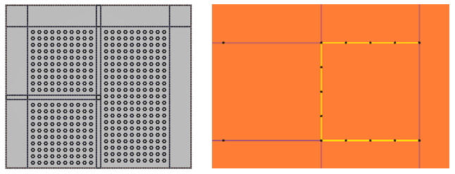
Step 1. Create a 2D layout with curves
Create a new project in Moldex3D Studio first and select the Solution as Solid and Encapsulation to enable corresponding functions. To establish a 2D layout, components such as chip and overflow, in the format of feature lines on the same Z location (substrate surface), click Import Geometry to import the IGS file or draw curves using functions in the Tool tab.
Note: Make sure the edge feature of each component is a closed loop.
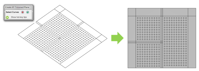
Step 2. Create the base plane
Moldex3D supports a 2D layout defined by curves or by faces (base plane) to simplify the procedure of component settings. For the base plane mode, click Trim Plane and select all the closed curves to generate the Base Plane. The Base Plane will enable surface mesh modification, which is more convenient for component creation in the wizard.
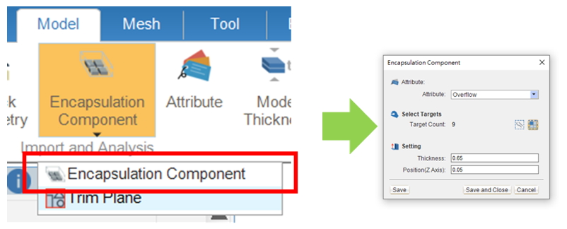
Step 3. Create IC components from the base plane
Click Encapsulation Component and choose Select faces. After attributing the material group, thickness, and Z-position, click Save to create a component and start the setting for another.
Once all the components are set up, the auto hybrid meshing can be executed, and the user can add, delete or edit components settings before the auto hybrid meshing is launched.
Note: There are 3 ways to edit component settings: double click on the 3D target generated from encapsulation components, right click on the target and select Edit attribute, or right click on the target from the model tree and select Attribute.
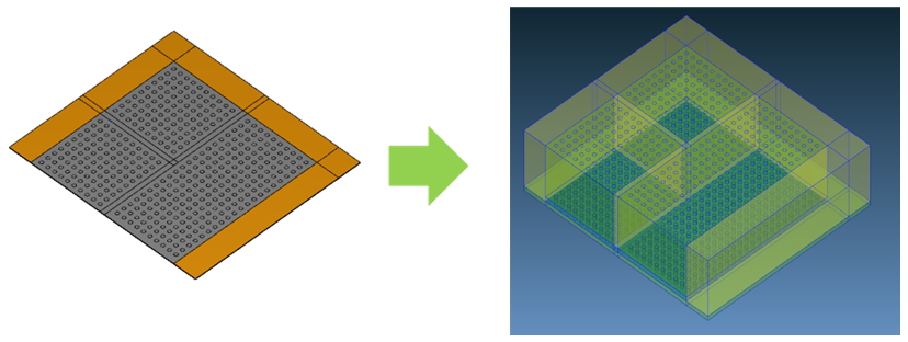
Step 4. Base mesh is created on the base plane with Auto Hybrid Wizard
If there is a base plane, the base mesh can be created. Before launching the Auto Hybrid Wizard, click Seeding to set the global mesh size on the base plane (click Apply to preview the seeding result). Also, users can choose the feature lines to set the local mesh size.
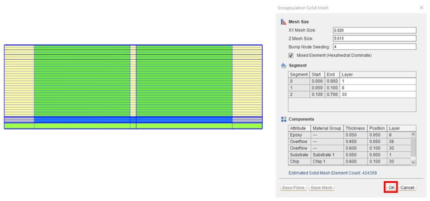
Then, click Generate to launch the Encapsulation Solid Mesh Wizard and click Base Mesh, and the base surface mesh result and estimated element count will be shown.
Note: One can refine and customize the surface mesh resolution further using the tools in Fix Mesh.
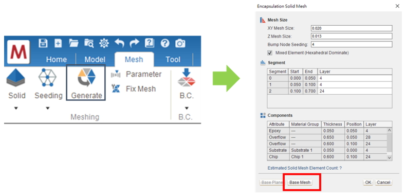
In the Segment table, the layer counts are calculated from the Z Mesh Size setting and it can be edited if needed (Start and End values are calculated from Z information of components). In the Component table, all IC components with the information of Material Group, Thickness, Position, and Layer are listed. The information in the Component section and solid element count will be updated when the parameter is modified. Once all parameters are confirmed, click OK to apply and create a solid mesh.
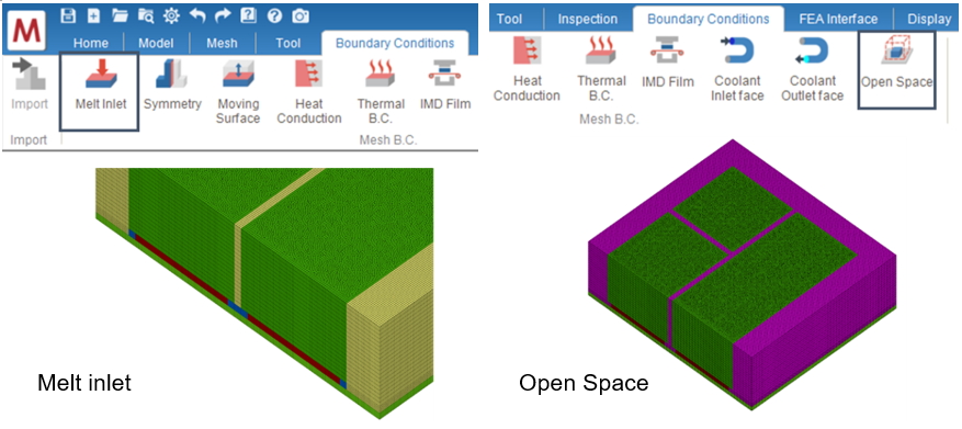
Step 5. Setting boundary conditions and exporting the model
After the solid mesh model generation, click Melt Inlet and Open Space and select the surface element to assign boundary conditions.
In the end of pre-processing, click the Final Check to check and freeze the solid mesh model. The check result will be shown after a few minutes, and the solid mesh is ready for analysis if no problems are found. One can then continue with other projects and analysis settings for IC encapsulation simulation.
Note: If users delete any part of the solid mesh, the corresponding 3D components should also be deleted, otherwise it will not be allowed in the final check.
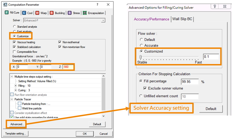
Other: Computation parameter setting recommendation
In the dotting or potting process, the gravity effect is considered, so it is recommended to set the solver accuracy as 0.1.