
In injection molding simulation of fiber-reinforced plastics, underpredicting the width of the fiber orientation core has been a long-standing problem, and the use of low-shear-rate yield-stress viscosity to improve core predictions has recently been drawing growing attention across the industry. CoreTech System (Moldex3D) took up this challenge early on: in 2016, its R&D team filed a US patent application for a method that uses yield-stress parameters to predict the core width of fiber orientation, which was granted in 2017 as US Patent No. US9573307B1 [1]. This article revisits the motivation behind that research, how it was validated, and its key findings.
Highly concentrated and relatively long fiber suspensions exhibit complex rheological behaviors. There is a particular broader core region of fiber orientation structure for fiber-filled parts in injection molding. However, there is a long-running problem of the academia and industry in which unsatisfactory narrow core results have been always obtained. Many people have tried to improve this issue by using 3D-CFD numerical methods and fiber orientation models, but the Moldex3D R&D team started the research by studying the viscosity behavior of fiber composites. Yield stress at low shear rates is a key characteristic of fiber composites, whereas general plastics without added fiber rarely have such a yielding. The well-known Herschel-Bulkley viscosity model [2] involves the yield-stress term and the Cross-WLF viscosity,
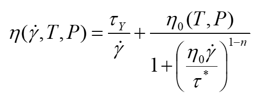
The team believed the reason for the poor predictions in the past was that the core occurred at low shear rates. However, the material viscosity model still used the Cross model, where the low shear rate region has Newtonian viscosity, meaning it does not change with shear rates. In reality, there is a yield stress term in which the viscosity increases as the shear rate decreases. Therefore, the team found that the viscosity of the core region was predicted too low in the calculation, making the flow not exhibit plug flow characteristics. This was the main reason.
However, for the previous 30 years regarding polymer processing simulations, no numerical calculations had considered the yield stress term in material models primarily affecting the fiber orientation distribution. The team was fortunate to recognize this importance, and through a series of studies and verifications, the team confirmed that increasing the yield stress viscosity directly increases the width of the core region. This is our US patent, and it has also been published in the prestigious academic journal Composites A [3].
Here, an injection molding system of the end-gated plaque with one measurement location at the center of the plaque was used (as shown in Figure 1). More importantly, the team could examine various slopes of the yield-stress viscosity, namely, Yield-1 (lower) and Yield-2 (higher) (as shown in Figure 2). It is obvious to present the flow-directional orientation component A11 distributions through the normalized thickness with the classic laminated structure of the anisotropic fiber orientation distribution (as shown in Figure 3): skin-shell–core–shell-skin. In the shell layer, the fibers were oriented along the flow direction by the stronger shear deformations; the others were random or transverse-aligned in the core region, where the deformations were weaker. Significantly, the team found that the core region of the fiber orientation distribution found at low shear rates was obviously widened with increasing the slope of the yield-stress viscosity.
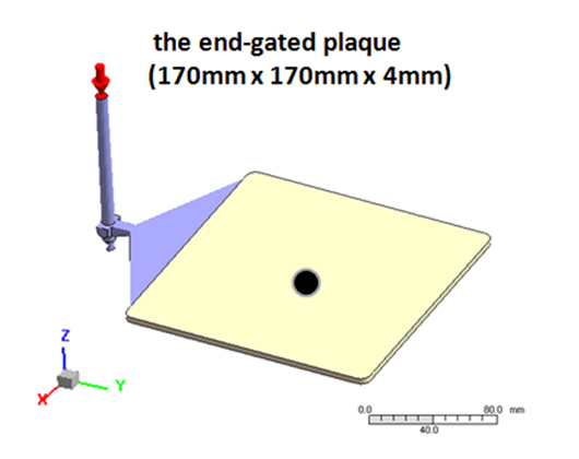
Fig. 1 Illustration of the end-gated plaque with one measurement location at the center.
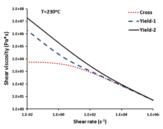 Fig. 2 Viscosity flow curve of the Yield-Cross-WLF model for various slopes of the low-shear-rate yielding term.
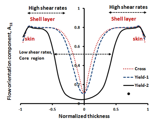
Fig. 3 Fiber orientation distributions.
Moreover, the iso-contour of melt time is displayed for various slopes of the yield stress viscosity (as shown in Figure 4). When the filling time approached 0.9 sec (or 90% filled-cavity), the melt front was somewhat convex parabolic for the Cross-WLF viscosity. By increasing the slope of the yield stress viscosity, the flat front became concave. Thus, such a simulation revealed the effect of the low-shear-rate viscosity on melt front.
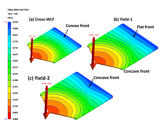
Fig. 4 Iso-contour display of melt front time.
Furthermore, the average velocity profiles at the center of the plaque are presented (as shown in Figure 5). The Cross viscosity resulted in a more pointed parabolic curve; by increasing the slow flow of the low-shear-rate yield-stress viscosity, the broader curve was very obvious, namely, the plug flow. In addition, the shear rate profile also presented that the core plateau had widened as a result of increasing the slope of the low-shear-rate shear-thinning or the yield-stress viscosity (as shown in Figure 6).
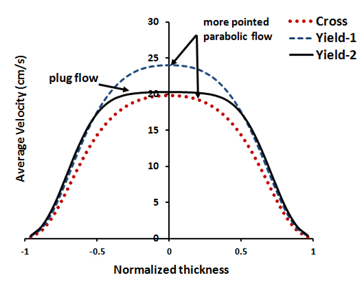 Fig. 5 Average velocity profile.
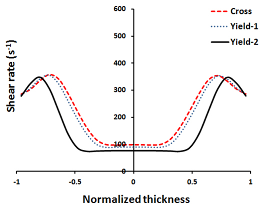 Fig. 6 Shear rate profile.
Ultimately, the team successfully demonstrated in injection molding simulations that by additionally considering yield stress viscosity at low shear rates, the width of the fiber core region can be effectively improved in the Herschel-Bulkley viscosity model aforementioned for predicting fiber orientation distribution. In recent years, we have further investigated the coupling calculation of viscosity and fiber orientation with rigorous theoretical derivation [4-7], finding that the extensional viscosity effect at low shear rates significantly impacts core width, similar to the yield-stress viscosity. The proprietary IISO (informed isotropic) flow-fiber coupling model is now highly recommended as an industry-proven solution. Leveraging its mature architecture, it has been widely adopted to deliver exceptional accuracy.