Challenges
To meet stringent thickness requirements; no flash or dust are allowed.
Solutions
Revised design with increased thickness in those two thin areas has been proposed to resolve the problems of original design.
- Hesitation phenomenon has been solved
- Sprue pressure and clamping force are reduced
- Stress is reduced
- Warpage has been improved
Benefits
The results have shown that Moldex3D not only reduces the research development costs but also leads better time management and product quality.
Ever since 2002, Chi Lin has successfully used Moldex3D software to develop more than hundreds of products, and the results have shown that Moldex3D helps not merely reduce the research development cost but also improve the RD time management and product quality. -Lee Mao-Song, President of Chi Lin Technology Co.
In recent years, Chi Lin has expanded its business into precise injection molding industry. It helps Chi Mei to produce a broad range of plastic products, including key components for TFT-LCD market. To meet various TFT-LCD products requirement, the geometries of plastic products can be very complicated. In addition, the question of production cost and efficiency makes the development and mold part design even more difficult. Nowadays, light, slim, and large sizes are the basic requirements for developing TFT-LCD products. For those manufactures, it is always a big challenge to meet these standards. In 2002, Chi Lin adopted Moldex3D simulation analysis technique to measure the feasibility of a product design plan in the early stage of product design process.
Moldex3D can detect flaws in original designs
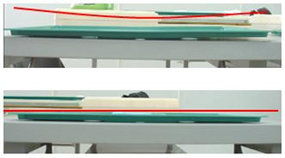
The sample product in discussion here is TFT-LCD plastic substrate. The flatness required should be controlled in less than 1.5 mm, and the problems of flash and dust are not allowed. There are two problems for the design: higher injection pressure can result in higher stress that further induces warpage problems, and flash occurs due to the lack of enough clamping force.
(1) Hesitation phenomenon
To better understand this product development, filling behavior is examined by short shot investigation numerically and experimentally. (Fig. 1, 3) show the simulation results and (Fig. 2, 4) are experimental results of original design. Obviously, both numerical prediction and experimental verification are in a good agreement. Results also show that hesitation happens in the center portion of the part. These figures also point out the melt front distribution and the location of weld line. In addition, from the advancement of melt front, the filling in the cavities can be observed all the time and the location of weld line and air trap can be predicted. Meanwhile, the short shot phenomenon can be estimated and this helps users to identify where the vents should be located.
|
|
|
|
|
|
(2) Clamping force is too high
The history curves of sprue pressure and clamping force (Fig. 6, Fig. 7). The sprue pressure is up to 114MPA (1 MPa=9.8kg/cm2) and the clamping force reaches to 1200 ton. Indeed, these history curves can be used to monitor the pressure behavior and the required clamping force during the filling/packing phases. Then the pressure in the runner and gates can be determined. Hence, the estimated pressure can provide users the reference of runner and molding design.
|
|
(3) Stress is too high
Shear stress distribution of the original design (Fig. 8). Clearly, it has demonstrated that high stress (>1Mpa) is the key factor of product warpage. In general, it should not be higher than 0.5 MPa (1MPa=9.8kg/cm2)
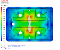 Fig. 8 Shear stress distribution
(4) Warpage problem is serious
The warpage displacement distribution ranged between –1.46~1.56 mm in Z-axis (Fig. 9). This result shows that the warpage is very serious and it doesn’t meet the criteria.
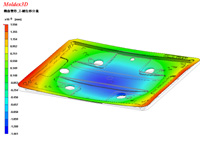 Fig. 9 Warpage prediction in the thickness (Z-axis) direction
Targeting the problems, end product improved significantly
The main problem of original design is there are two thin areas in the part. Therefore, this revised design with increased thickness in those two areas has been proposed to resolve the problems of original design.
(1) Hesitation phenomenon has been solved
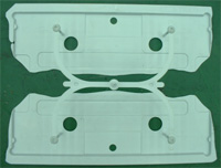
Those figures of melt front and real mold trial (as shown from Fig. 10~14) clearly indicate the hesitation phenomenon has been solved.
 |
 |
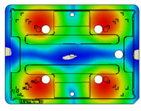 |
Fig. 10 Melt front prediction of revised design |
Fig. 11 Real short shot sample of revised design |
Fig. 12 Melt front prediction of revised design |
|
|
|
|
Fig. 13 Real short shot sample of revised design |
Fig. 14 Melt fron iso-contour of revised design |
|
(2) Sprue pressure and clamping force are reduced
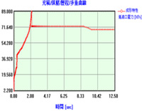
As illustrated, the stress goes down to 89MPA (1 MPa=9.8kg/cm2) and the clamping force required is decreased to 920 ton (Fig. 15, Fig. 16).
 |
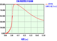 |
Fig. 15 Revised design: history curve of sprue pressure |
Fig. 16 Revised design: history curve of clamping force |
(3) Stress is reduced
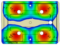
The shear stress distribution for the revised design (Fig. 17). The shear stress is smaller than 0.5 MPa in this whole area. Clearly, the high shear stress portion in the original design is removed.
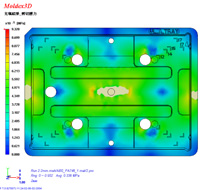
Fig. 17 Shear stress distribution of revised design
(4) Warpage problem is improved
Finally, the warpage distribution in thickness direction (Fig. 18). The warpage amount is controlled between –0.52 and 0.56 mm. Obviously, the warpage problem is greatly improved.
|
|
Save time and money
By using Moldex3D to perform numerical simulation for the injection product design and development, Chi Lin can catch the crucial problems at the right time. Thus the production cost is dropped and the competence is increased. The president of Chi Lin Technology Co., Mr. Lee, said, “From the past few years, the competition in the TFT-LCD monitor market was becoming extremely fierce. Knowing how to reduce the product manufacturing costs and increase the speed and efficiency in the production line is certainly an important issue for every manufacture. Therefore, the implementation of Moldex3D simulation analysis technology will meet these criteria. Ever since 2002, Chi Lin has successfully used Moldex3D software to develop more than hundreds of products, and the results have shown that Moldex3D helps not merely reduce the research development cost but also improve the RD time management and product quality.”
*About CHIMEI Group: Since its founding in 1959, Chi-Mei Corporation has been a major player in the Petro-Chemical industry for more than 40 years. Chi Mei was the first acrylic sheet manufacturer in Taiwan. Its ACRYPOLYR was called the Acrylic Sheet of Taiwan, and the chairman Hsu became known as the “Father of Taiwan Acrylic”. Chi-Mei Corporation affiliates has combined net sales over 10.5 billion US Dollars in 2006, and has employees more than 36,000.
* This case was published in November, 2006. Moldex3D News No. 15
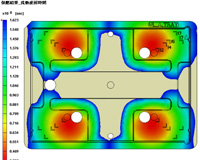 Fig. 1 Melt front prediction of original design
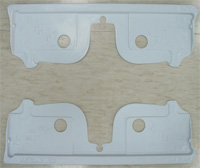 Fig. 2 Real short shot sample of original design
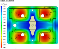 Fig. 3 Melt front prediction of original design
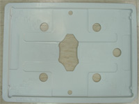 Fig. 4 Real short shot sample of original design
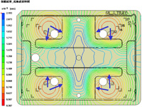 Fig. 5 Melt front iso-contour of original design
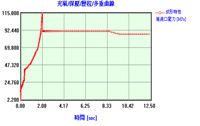 Fig. 6 The history curve of sprue pressure
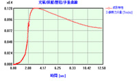 Fig. 7 The history curve of clamping force
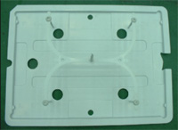
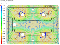
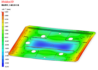 Fig. 18 Warpage distribution in thickness