
Moldex3D R14.0 provides Hot Runner Steady (HRS) analysis designed for hot runner system simulations. It supports a quick steady state analysis for a complex hot runner system in order to save time and speed up the design process. HRS Analysis can significantly save the simulation time spent for a high cavitation hot runner mold design. It can also help users efficiently obtain the balance ratio of the hot runner layout design, and enhance the prediction capability for the cycle-by-cycle viscous heating to attain a more realistic hot runner temperature distribution.
In the texts below, two step-by-step HRS analysis examples will be given:
1. Using HRS Analysis to Optimize the Hot Runner Design without Simulating the Cavity Filling
HRS analysis can help users optimize their hot runner design with multi-cavity models by simulating the filling behavior in the hot runner channels to attain information like flow rate and balance ratio. Without simulating the cavity filling, HRS Analysis facilitates greater iteration calculation efficiency and provides a much faster solution for hot runner design optimization.
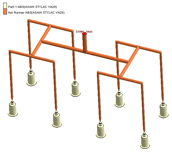
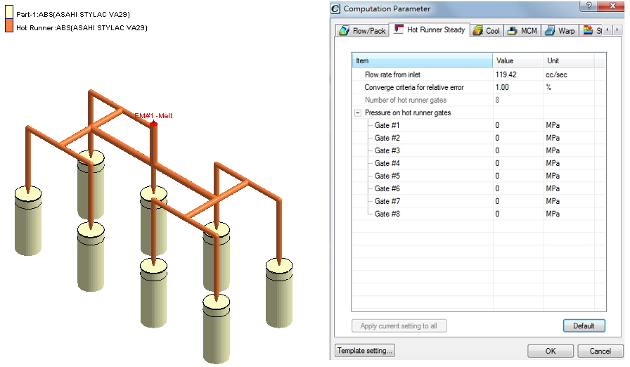
Step 1. Create an Injection Molding Project with a mesh model including at least melt entrances, cavities, and hot runners. Although HRS analysis neglects the cavities during calculation, users still have to include them in the mesh model.
Note: License for the Advanced Hot Runner module is required to set up Hot Runner Steady function in Computation Parameter and Analysis Sequence.
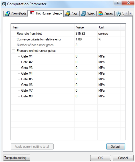
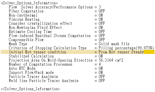
Step 2. Setup HRS Analysis by specifying the flow rate from the inlet, converge criteria for relative error, and pressure on hot runner gates under Hot Runner Steady tab in Computation Parameter.
Note: In the CAE mode, the default value of the flow rate from the inlet is defined as the cavity volume divided by the filling time. In the machine mode, the default value of the flow rate from the inlet is defined as the cavity volume divided by the stroke time.
Note: The pressure on hot runner gates indicates the outlet resistance of each gate (0 MPa as default). Users are advised to run a simulation on one single cavity mold (only with a melt entrance but without a runner system) prior to HRS Analysis. It will provide a better estimation of the pressure at the hot runner outlets in HRS analysis (without cavities) and still save the time of simulating all cavities along with hot runner systems.
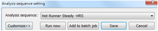
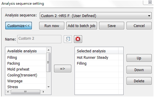
Step 3. Select HRS only in Analysis sequence setting and run the simulation.
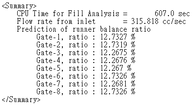
Step 4. Check the flow rate shown at the tip of each hot runner gate and further check the prediction of the runner balance ratio in HRS log file. According to these two referenced results, users can then modify the geometry of the hot runner layout, such as changing the hot runner diameters or lengths in particular regions in order to attain a balanced flow if needed.
Note: HRS analysis provides several analysis results, but the key results are the flow rates and the runner balance ratio predictions.
Step 5. Repeat Step 1-4 if the hot runner design is modified.
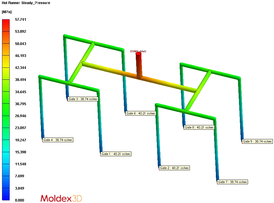
Gate contribution Pressure distribution
2. Running Filling Analysis after HRS Analysis to Attain More Realistic Initial Hot Runner Conditions
In contrast to Filling analysis, HRS analysis takes the accumulated shear heating effect after several cycles (until it becomes steady) into account, including the non-uniform or non-symmetric temperature distribution along the hot runner systems. As a result, if the Filling analysis is performed after HRS, it will have a better assumption of the initial hot runner conditions; thus, a more accurate filling prediction can be attained.
The procedure to perform this simulation is as follows:
Step 1. Re-do Step 1 and 2 in the previous section (we use a different model this time).
Step 2. Set the analysis sequence: Run HRS analysis first, and then Filling Analysis.
Note: This sequence is not in the default Analysis Sequence setting, but the users can customize it as shown below:
Step 3. Check out the Filling analysis results.
Note: By comparing the temperature and the melt front time results as well as the filling logfiles, users can clearly observe the advantages of applying HRS analysis prior to Filling analysis.
| Filling Analysis | HRS-Filling Analysis |
| Filling Log File (showing if it takes initial hot runner condition from HRS) | |
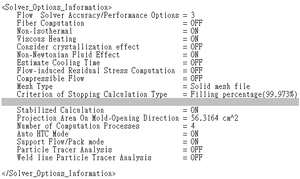 |
 |
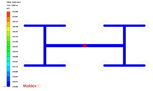
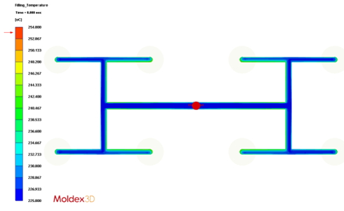
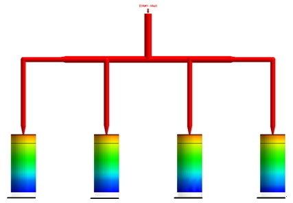
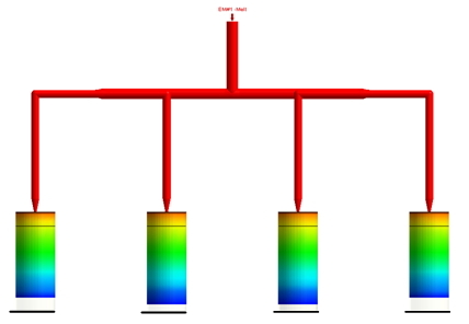
| Initial Filling Temperature | |
 |
 |
The initial hot runner temperature is obviously uniform and symmetric |
The initial hot runner temperature is obviously non-uniform and non-symmetric |
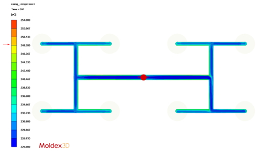
| Filling Temperature at End of Filling (EOF) | |
 |
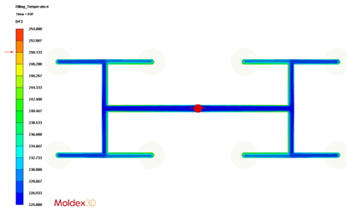 |
| Melt Front Time | ||
 |
 |
|
The filling pattern looks quite balance |
Imbalanced filling pattern is detected with the proper initial hot runner temperature |
|