
In general, the effect of wall slip on the cavity surface is ignorable, but in some cases (e.g. light guild plates, thin products, or extremely smooth polished mold walls), this wall slip behavior will have a great impact on the flow behavior and should be considered in the analysis. Moldex3D R13.0 allows users to simulate the wall slip impact on the cavity surface in which users can specify the wall shear stress threshold and the friction coefficient while setting the wall slip boundary condition. The larger the friction coefficient or wall shear stress threshold, the rougher the cavity surface is; thus, it will result in a higher flow resistance.
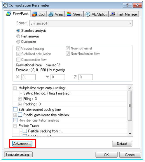
Step 1. To set the wall slip boundary condition before starting the analysis, open the computation parameter dialog and click Advanced… under Flow/Pack Tab.
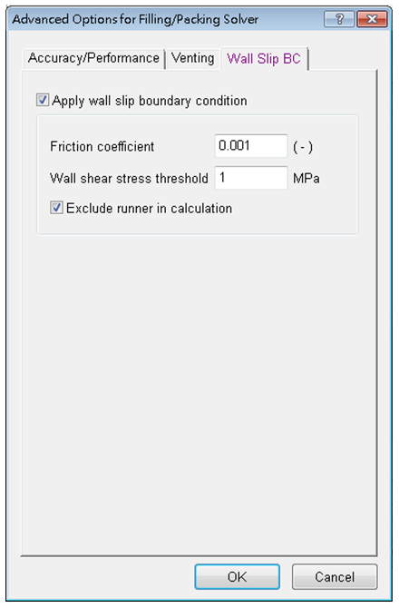
Step 2. Check Apply wall slip boundary condition, and specify the Wall Slip BC parameters. The friction coefficient indicates the relations between flow field, frictional drag, and wall shear stress threshold. The critical wall shear stress means the critical shear stress at the moment when the flow behavior switches from non-slip to slip. Click OKto apply the setting.
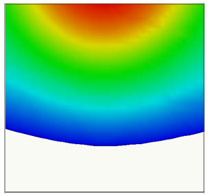
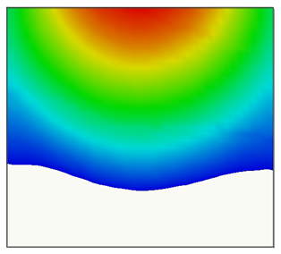
Step 3. After the filling analysis, compare the results of the case ignoring the wall slip impact and those of the case considering the wall slip impact. As shown in the pictures below, the melt front time results with and without considering the wall slip impact are different.
Wall Slip Demo (Melt Front Time)
 |
 |
Without wall slip boundary condition settings |
Without wall slip boundary condition settings |