Resin transfer molding (RTM) is one of the most prevalent processes available today in the composite product manufacturing since it can reduce the production time and produce high-strength fiber reinforced plastic (FRP) parts. In addition, a sandwich structure, multilayer fiber mats with core material(s), have been a prominent design for wind turbine blades and aircraft part manufacturing in order to further strengthen the structural properties of FRP parts. Thus, we intend to gain a comprehensive understanding of using a sandwich structure design in the resin transfer molding (RTM) process in the following study.
The traditional 2D/2.5D simulation tool has its limitations on fully capturing the true geometry of the part and the differences between the material properties in the thickness direction; thus, the accuracy of the 2D/2.5D simulation results may be compromised. Therefore, we have established a true three-dimensional (3D) numerical simulation tool that captures the full geometric values of the simulated parts and we are able to observe the resin flow in the mold that is suitable for all kinds of fiber compositions.
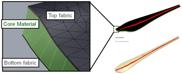
 Fig. 1 Sandwich structure design of a wind turbine blade
As shown in Figure 1, this sandwich structure design of a wind turbine blade is a multilayer fiber mat design with a core material and a skin material. The corresponding material parameters are listed in Table 1. In this case, the fabric, with a thickness of 1.24mm, is placed on top and bottom of the core material. An inlet is designed in the middle of the structure, passing through the whole blade. The resin will flow from the inlet in the middle to both sides of the blade. We apply SWANCOR 2502-A/B as the injected fluid with the constant pressure of 1 atm.
| Fabric | Core | |||
| Thickness[mm] | 1.24 | 25 | ||
| K11[m2] | 1.80E-11 | 5.61E-11 | ||
| K22[m2] | 1.23E-11 | 1.97E-10 | ||
| K33[m2] | 3.27E-12 | 1.97E-10 | ||
| ϕ | 0.44 | 0.11 |
Table 1 The core and the skin material parameters
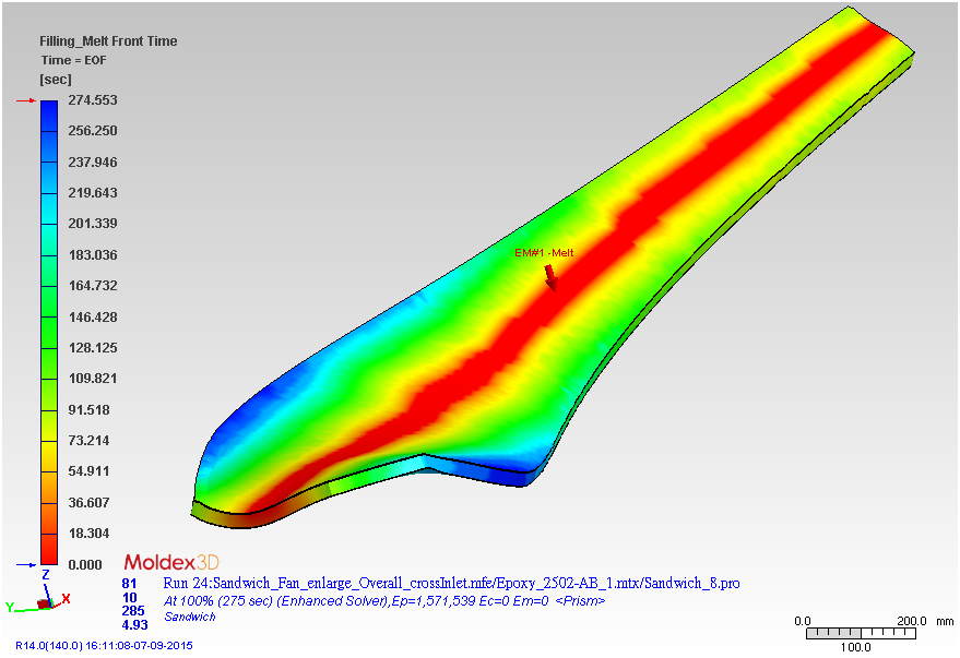
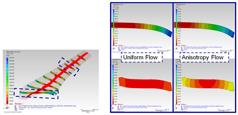
Figures 2 & 3 are Moldex3D’s 3D simulation results of the sandwich structure design for a wind turbine blade. Figure 2 shows a non-isothermal 3D flow simulation that includes the different curvature geometric values and material parameters. Figure 3 shows the 3D flow analysis of a sliced section of the part in the thickness direction. It is observed that the resin flows faster in the core region than in the fabric region. It is due to the higher permeability and lower porosity of the core material, resulting in a faster flow phenomenon in the core region.
 Fig. 2 Moldex3D 3D simulation: Flow front time at the end of filling stage of the sandwich structure design for a wind turbine blade
 Fig. 3 The 3D flow analysis of a sliced section of the part in the thickness direction
In addition, the following simulation results clearly demonstrate that traditional 2D simulation only considers the flow behavior in the in-plane direction. The curvature geometric values cannot be truthfully captured and reflected in the computation of 2D simulation. The variables of the flow behavior in the thickness direction will be treated to be the same in 2D/2.5D simulation, which will ultimately create a great discrepancy in the result when comparing with the actual molding scenario since the influence of different material permeability and porosity is not considered.
 Fig. 4 The comparison of the flow front results in the thickness direction between the uniform (2D) and the anisotropy flow (3D) conditions
In conclusion, from the comparison above, we can clearly understand the impact of the different material properties and characteristics in the thickness direction on the actual flow behavior. As a result, we can conclude that 3D simulation is the only simulation technology that can fully capture a complex geometric design and truly reflect the intricate, interchangeable material mechanisms in a multilayer fiber design structure in the RTM process. In addition, it is necessary to consider how different porous materials influence the production of RTM products. Using an advanced 3D simulation will include different flow parameters in all dimensions and the flow behavior in the mold can be visualized which further helps improve and optimize the RTM process.