
Black lines are one of the most common surface defects in Metal Injection Molding (MIM). They are caused by powder binder phase separation, which results in non-uniform distribution of the powder. Most of the black lines have already occurred while injecting the feedstock into the cavity and can be observed on a part surface. Usually the defects cannot be identified until the end of sintering, which is too late.
Areas marked by black lines show low powder concentration and relatively high binder concentration. During sintering, these areas will result in visual defects or weaken the mechanical performance of the parts. As product design has become increasingly complex, it is not cost effective to use the trial and error approach for solving mold defects like black lines. Therefore, one needs to understand the properties of the green part before sintering to ensure quality.
The following case study of a fan-gate MIM part will introduce how to utilize the Moldex3D Powder Injection Molding (PIM) solution to eliminate black lines. According to the powder concentration and shear rate analysis results, the part has uniform powder concentration on the surface. However, a higher shear rate has been identified near the gate and resulted in non-uniform powder concentration; these areas are often marked by black lines. Through the Moldex3D PIM solution, users can easily build links between mesh models, material properties and processing conditions. Most importantly, users can understand the cause and predict potential areas of black lines through optimizing process parameters with Moldex3D.
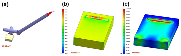 Fig. 1 (a) the fan gate geometric model (b) the result of powder concentration distribution (c) the result of shear rate distribution
Below is the comparison showing a good correlation between the simulation results of the black lines and the real world molded part. The results indicate that CAE simulation solutions can help users demonstrate and validate their part and mold designs before actual production. To find out more information about Moldex3D, please go to www.moldex3d.com or fill out the online inquiry form.
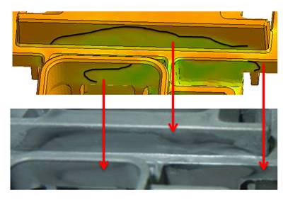 Fig. 2 The comparison between Moldex3D simulation results of black lines and the real molded part