
Specially thanks to Lite-On Technology Corporation for providing experimental data of gas penetration and fruitful discussions.
Jim Hsu
In gas-assisted injection molding (GAIM) process, “gas fingering behaviors” are one of the most common issues. This happens when gas bubbles penetrate unevenly into the core of the plastic parts and form finger-shape branches out of the desired gas channel. Severe fingerings can lead to significant reductions in part stiffness [i]. According to the investigation of GAIM, gas fingering behaviors are mainly caused by secondary gas penetration [ii].
Short shot method was applied in GAIM at early stages to hollow the product using assistant gas to save materials and reduce product weight. When GAIM ribs are used to enhance the strength of a thin plate, the ribs will become gas channels and will be hollowed by auxiliary gas. If the ribbed plate geometry is not well-designed, the product strength will be significantly reduced because of improper hollowing [iii].
To address the warpage issue, “full shot gas-assisted injection molding” is often applied to compensate shrinkage and improve product quality. In this molding process, auxiliary gas enters the mold when the cavity is full of melt. Thus, the gas penetration way can only be secondary penetration, so the hollowed area is relatively small. Meanwhile because of the gas hollowing, the residual stress of the hollowed area can be reduced, and sink marks can also be reduced[iv]. However, the secondary penetration behaviors in full shot gas-assisted injection molding will lead to complicated gas fingering behaviors.
This case features the simulation of a complicated product geometry using full shot injection molding. The part in this case is a printer cover (Fig. 1). It requires good flatness and strict deformation specification, or the paper cannot be sent successfully. In this case, auxiliary gas will hollow the structural ribs to avoid sink marks and enhance the mechanical properties of the area after the mold is filled with melt. The material used in this experiment is amorphous transparent Acrylonitrile Butadiene Styrene (ABS), which facilitates the gas penetration comparison of simulation and experimental results as well as the evaluation of secondary penetration prediction accuracy. The simulation tool used in this case is Moldex3D, and the material parameters are Moldex3D default values.
In this full shot gas- assisted injection molding process, gas enters the cavity when the melt starting shrinking and release space for the gas penetration. However, the melt has already occupied most of the flow space, so the gas will be released from the gas channels to other area where gas channels are not required. Therefore, obvious gas fingering behaviors will occur. Severe fingering behaviors will significantly reduce product stiffness, impact strength and stability. Thus, if we can find the areas that fingering behaviors tend to occur, we will be able to decide proper entrance of the gas needles.
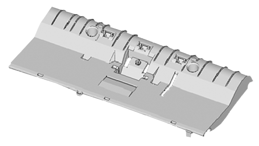 Fig. 1 The part geometry of a printer cover in this case
Because of the double-gate runner system design in this case, the melt front will flow from the gates to the thin area, and the flow path will be radial. As shown in Fig. 2 and Fig. 3, the melt front simulation and experimental results are very consistent at both 2 seconds and 2.84 seconds.
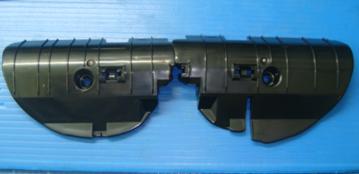
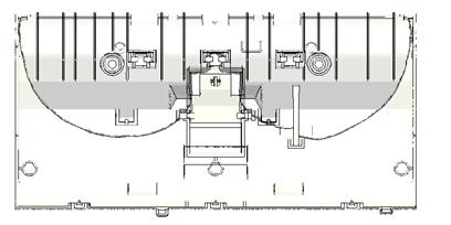 Fig. 2 The experimental (above) and simulation (bottom) results of the melt front at 2 seconds.
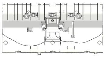 Fig. 3 The experimental (above) and simulation (bottom) results of the melt front at 2.84 seconds.
As shown in the comparison of the experiment and simulation results (Fig. 4), after the cavity is filled, there will be 3 gas inlet points, where 3 fingering behavior areas (hollowing branches) will occur. Branch #2 occurs at Gas needle #2 in the center of the bottom; Branch #1 and #3 occur at Gas needle #1 and #3 at the left and right sides. Gas needle #2 is the closest to the melt entrance, so the melt temperature here is the higher when the gas enters. Thus, the flow resistance is reduced, and the fingering behavior here is the most obvious. On the other side, the melt temperature at the rest of the gas needles is lower, and the gas fingering behaviors are less obvious. This can be observed in the iso-surface graph of the shrinkage rate (Fig. 5). The average shrinkage rate values are mainly at Gas needle #2.
(a) (b)
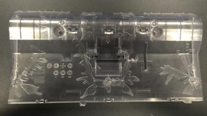
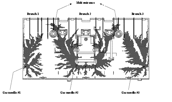 Fig. 4 The experimental (a) and simulation (b) results of the gas hollowing of the printer
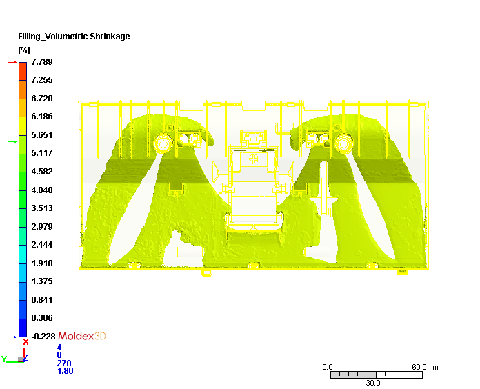 Fig. 5 The simulated iso-surface graph of the average shrinkage rate when the assistant gas enters
The fingering behavior area cannot be easily measured in the experiment. Therefore in order to quantify the size of the fingering behavior area, we define the shadow area of the fingering behaviors according to the study[v]as below: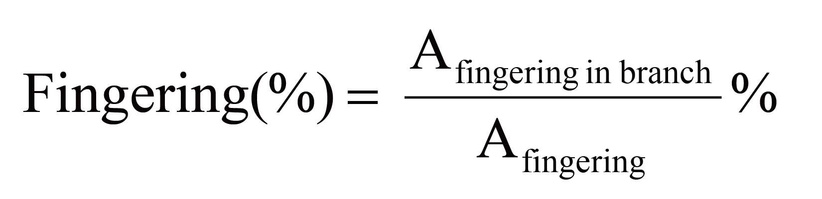
![]() is the total shadow area of the fingering behaviors from top view. Comparing the fingering behavior area in the experiment and simulation, we can find a consistent trend (Fig. 6).
is the total shadow area of the fingering behaviors from top view. Comparing the fingering behavior area in the experiment and simulation, we can find a consistent trend (Fig. 6).
The secondary gas penetration behaviors in the simulation and experiment results are validated consistent. Thus, we know that Moldex3D Gas-Assisted Injection Molding Module can effectively predict the gas fingering behavior distribution, and help users improve product structure stability.
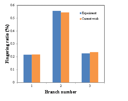 Fig. 6 The comparison of the fingering ratio in the experiment and simulation results
[i] X. Lu, H.H. Chiang, L. Fong, J. Zhao and S. C. Chen, “Study of “gas fingering” behavior in gas‐assisted
injection molding”, Polymer Engineering & Science, 39 (1) , 62-77, 1999
[ii] K.Y. Lin and S.J. Liu, “The influence of processing parameters on fingering formation in fluid‐
assisted injection‐molded disks”, Polymer Engineering & Science, 49 (11), 2257-2263, 2009
[iii] R.D. Chien, S.C. Chen, M.C. Jeng and H.Y. Yang, “Mechanical properties of gas-assisted injection
moulded PS, PP and Nylon parts”, Polymer, 40(11), 2949-2959, 1999
[iv] S.Y. Yang, C.T. Lin and J.H. Chang, “Secondary gas penetrations in ribs during full‐shot gas‐assisted
injection molding”, Advances in Polymer Technology, 22(3), 225-237, 2003
[v] S.J. Liu and S.P. Lin, Factors affecting the formation of fingering in water‐assisted injection‐molded
thermoplastics, Advances in Polymer Technology, 25(2), 98-108, 2006
 |
Dr. Jim Hsu
|