
The evolution of plastics molding simulation technology began from the plastics filling simulation, and then extended to runner, gate and cooling system simulation. Next, the effects of inserts and even the whole moldbase were also considered in the simulation. In today’s highly competitive market, the demand of true mold simulation is getting higher, since the quality of moldbase design can highly affect the product yield rate, for example, the cooling system layout. If the temperature distribution on the mold plate is not uniform, mold deformation might occur and cause flash. Thus, the yield rate will decrease. Take air trap issue as another example. Plastics filling simulation can predict the possible air trap locations. With appropriate mold designs including parting lines, parting surfaces, ejectors and slides put near the possible air trap locations, there will be good venting space to prevent air traps and burn marks as well.
Advanced users need very detailed analysis results, so the comprehensive mold mesh is necessary. However, it costs experienced users significant time and efforts in mesh building in order to create matching solid mesh among every component. As the result, there were very few successful cases of true mold analysis.
In simulation analysis process, Moldex3D Pre-processor allows users to import the geometry model of an entire mold, and build detailed mesh elements for every mold component. Moldex3D R14.0 starts supporting continuous simulation of the non-matching mesh between the part and part insert. It enables users to save time and efforts in matching the mesh. Moldex3D R15.0 extends non-matching mesh simulation capability to the solid mesh generation among the part, part insert and moldbase. In the latest version, Moldex3D R16, non-matching mesh simulation further includes the mold insert, as well as the new mold plate attributes including fixed and movable mold plates. Through the non-matching mesh technology, the solid mesh of the complete mold system can then be automatically generated.
A case of utilizing non-matching mesh in simulating a complete mold system is interpreted below.
- Simplifying the complete mold model: Mold designs usually include many tiny components, which have very little effect on mold simulation analysis. Thus, in order to reduce mesh elements and analysis time, users can simplify the model by removing the screws or filling the screw holes in the CAD models first.
- Import the simplified model to Moldex3D Designer BLM and set attributes: Set the attributes of the part, runner, cooling channels and mold inserts respectively, and utilize the new mold plate attributes to set the fixed and movable mold plates. It can show or hide the items with set attributes (Fig. 1).
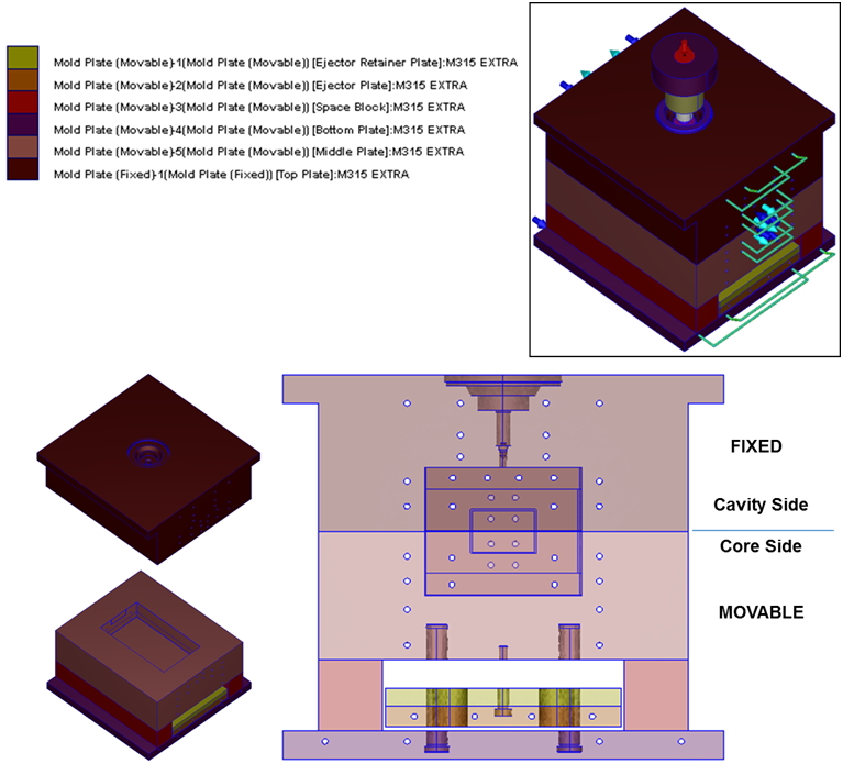
Fig. 1 The settings of complete mold and mold plate attributes
- Node seeding: Set node seeding from the cavity, mold insert to mold plate. The new node seeding capability can automatically bring the node seeding data of the cavity or mold insert edges to the adjacent edges of the mold insert and mold plate. This function enhances the node seeding efficiency of complete mold with multiple components, and reduces size gaps of the node seeding density between the adjacent components (Fig. 2).
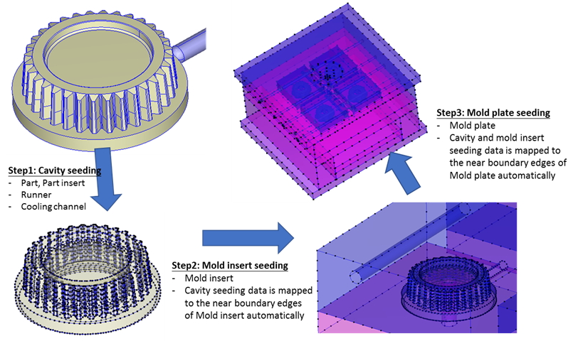
Fig. 2 The three-step node seeding data will be brought to the analysis of the next item.
- Build solid mesh: Click the button for generating solid mesh, and the solid mesh of the complete mold model will be automatically generated.
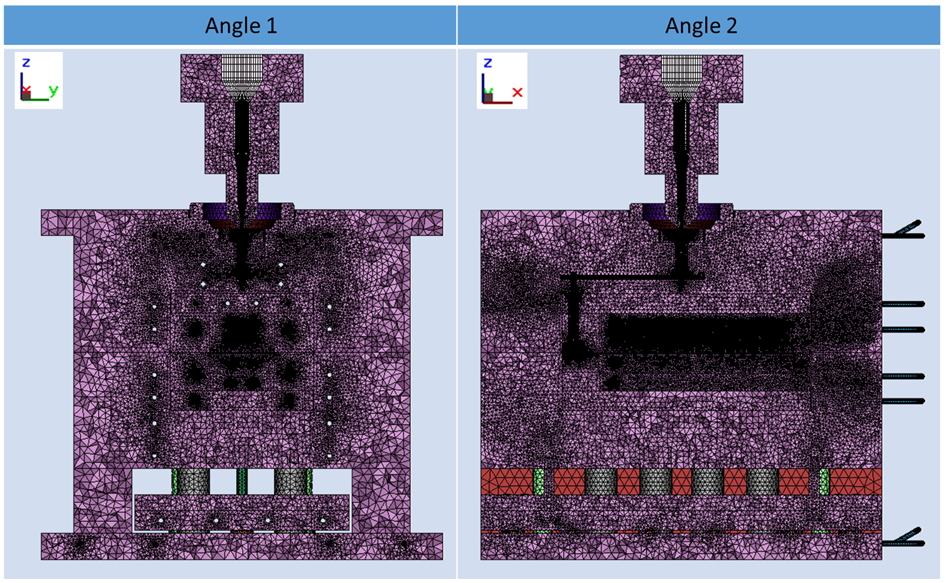
Fig. 3 The solid mesh section of the complete mold model
- Export MFE file: The software will automatically check the mesh model before saving it into the file. Warning will pop out if mesh cell intersections detected although Non-matching mesh technology allows small amount of mesh cell intersections. When the intersection amount is too large, there might be such issue as the non-hollowed tunnels, which has to be modified to prevent analysis problems (Fig. 4).
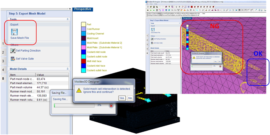
Fig. 4 Mesh cell intersection check before mesh export
- Mold filling analysis: The part material in this case is PC, and the mold plate material is M315 EXTRA. The default melt temperature and mold temperature are 290 °C and 105 °C. By observing the mold temperature of the fixed and movable mold plates, we can find good temperature continuity of the non-matching mesh model. Heat can be delivered between different mold plates (Fig. 5).
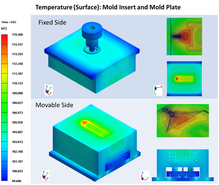
Fig. 5 The temperature distribution of the mold inserts and mold plates
The complete mold analysis in Moldex3D R16 considers the true mold design data of the complete mold model analysis. The new mold plate attribute function enables users to set attributes of fixed and movable plates, and the advanced non-matching mesh technology facilitates rapid solid mesh generation of the complete mold system. The comprehensive mold analysis results provide customers more required simulation data for mold design. Thus, they are able to reduce mold trial times, efficiently speed up mold development, and enhance product yield rate.