
Thank you to Mr. Gorka Jaio from Batz for providing experimental data of water penetration and stimulating discussions. And thank you to my colleagues Henry Huang and William Wu for offering feedback and suggestions along the way.
Jim Hsu
Fluid-assisted injection molding (FAIM) process applies a technique to let assisted fluid enter after plastic injection molding and form a hollow structure inside products. FAIM can produce hollow parts with good dimension control that conventional injection and blow molding cannot achieve. Also, unlike traditional injection molding, the fluid can hold pressure from the inner part for better pressure distribution across thickness and therefore can produce better surface finishes, reduce shrinkage and residual stress and achieve higher dimensional accuracy. As such, the technique of FAIM keeps getting promoted with lots of new patents of process methodology all over the world [i, ii, iii].
According to the amount of plastic melt injected into the cavity, we can categorize the FAIM process generally into two types:
- Short-shot method: In this early developed FAIM application, the amount of the injected plastic is less than the cavity space and rely on fluid to press and full fill the cavity. This method is very suitable for rod shape or large size hollow products, and the hollow rate is normally lower than 35%.
- Full-shot method: With injecting the full amount of resin into the cavity space, assisted fluid then only supports to pack more material for shrinkage during the cooling stage and collaborates with different techniques (to be discussed later) for better core-out control. Thus, it allows a wider range of hollow rate, and can effectively improve sink mark and warpage issues for thin-plate shaped product.
Full-shot FAIM process is a more favored technique among manufacturers since the short-shot method is more likely to cause defects like hesitation flow marks. For example, push-back is a common technique of water-assisted injection molding (WAIM) (shown in Fig. 1). In this molding method, the entrances for plastic melt and for water are at two different sides of the cavity, and water is injected after the cavity is fully filled to push the plastic melt back into the injection unit. With this technique, it can not only eliminate the flow mark issue in the short-shot method but also reduce material waste by reusing the resin that flows back to the injection unit and taking overflow out from the cavity. However, this technique requires a special design of the nozzle to prevent the melt from flowing back during the filling stage. Also, the melt and fluid entrances at the two sides must be considered in the product design.
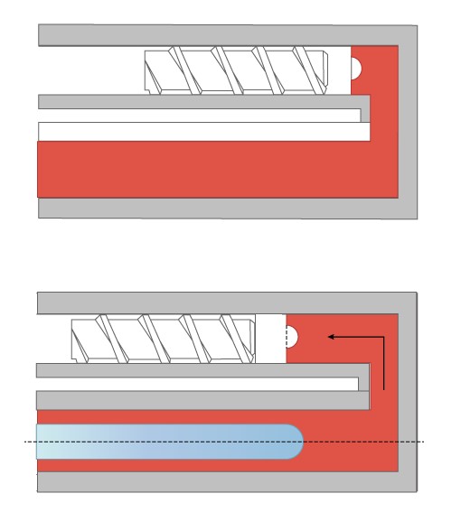
Fig. 1 Illustration of the push-back method [i]
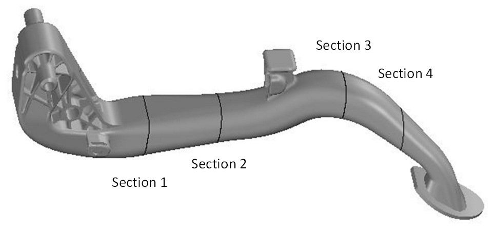
This study aims at simulating a car pedal molded with the push-back method. The wall thickness of the pedal is uneven because it needs to meet strength and mechanical requirements (see Fig. 2). The polymer melt applied in this study is PA6, a crystalline material with default properties provided by Moldex3D as Table 1 listed.
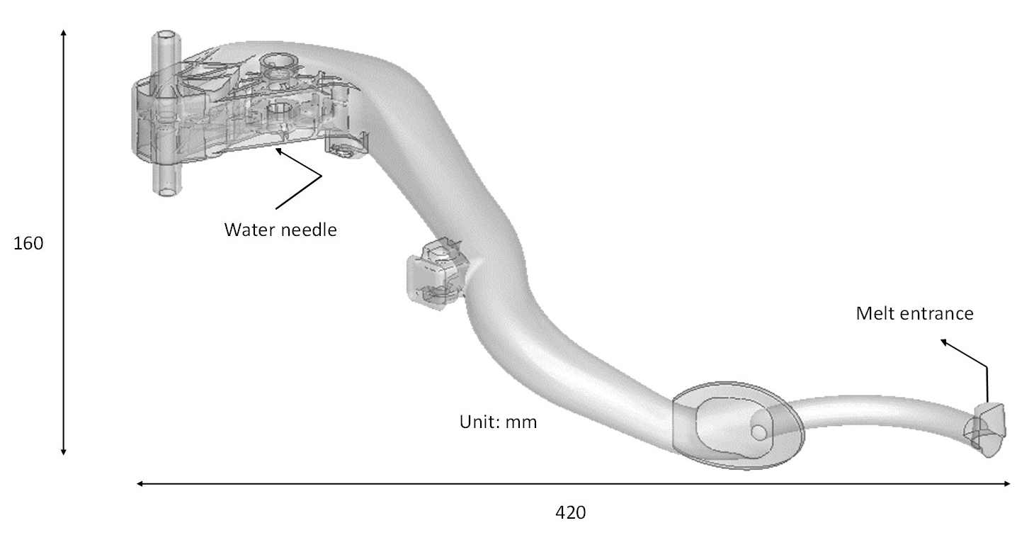
Fig. 2 Illustration of the pedal geometry
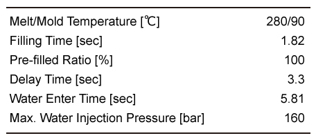
Table 1 Process condition of the pedal
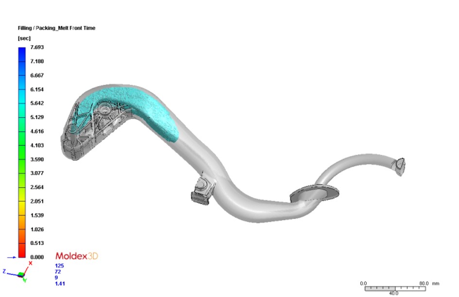
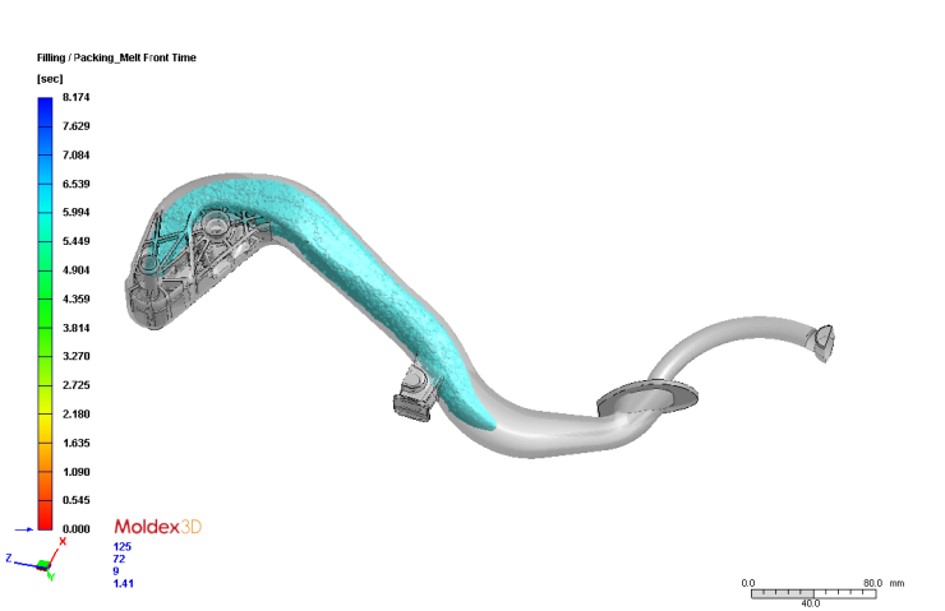
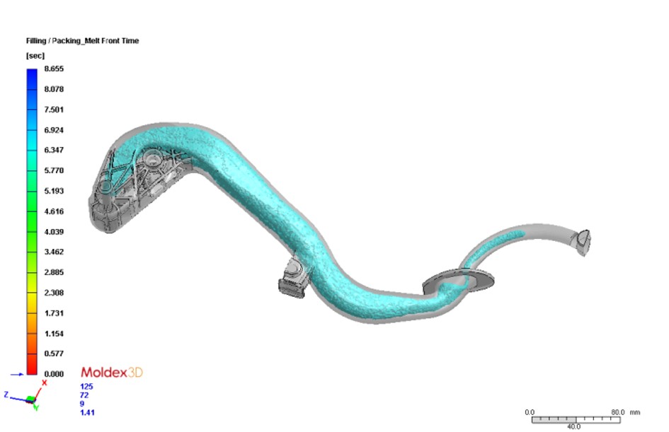
The main characteristic of the push-back method is opening the nozzle to allow the melt flowing back through the injection unit when the assisted fluid enters. During the simulation, the pressure at the melt entrance is set at zero when the water injection starts. As such, the overall distribution of the pressure gradient will reverse, higher from water injection and lower near the melt entrance. This behavior can be observed through the variation of pressure distribution during water penetration shown in Fig. 3. The streamline plot in Fig. 4 demonstrates the effect of a pressure gradient to water penetration and shows the potential pathway of assisted water using velocity direction.
 |
 |
 |
| Filling Time: 7.7 sec | Filling Time: 8.1 sec | (a) Filling Time End |
Fig. 3 The Water Penetration and Pressure Distribution Result at Different Times
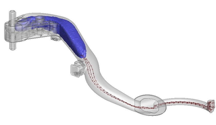
Fig. 4 Streamline Plot of Assisted Water Penetration at the filling time of 8.3 sec
When the assisted water enters, the variation with the time of water pressure and back-flow rate at melt entrance can be obtained in Fig. 5. The result clearly shows that the back-flow rate is influenced by the control of water pressure. When it reaches the end of core-out (filling time: 8.7 sec), the water pressure will be reduced to control the amount of plastic flowing back and prevent water from flowing back to the nozzle, so the water penetration will remain in the cold runner. Fig. 6 shows the simulation result matches well with the experiment, the back-flow valve will close at the filling time of 8.8 sec. Upon closing the valve, the pressure of the assisted water will be increased.
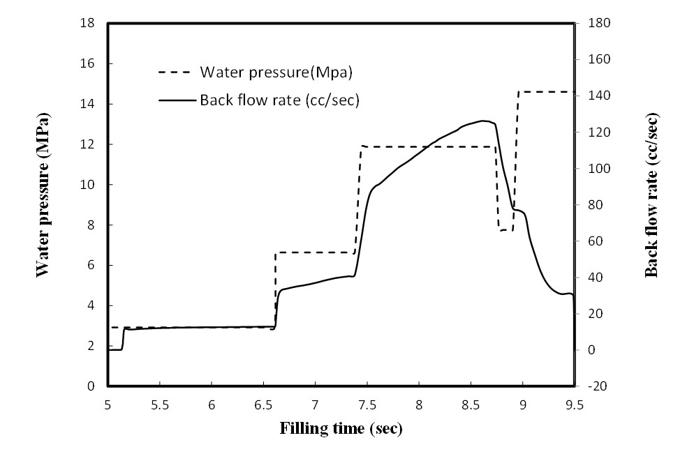
Fig. 5 The variation of the water pressure and flow rate of the push-back Process
 |
 |
| (a) | (b) |
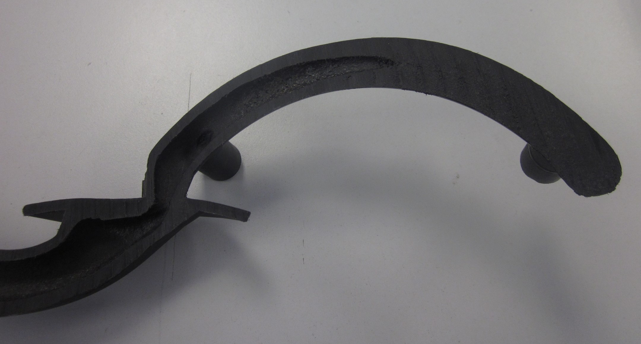
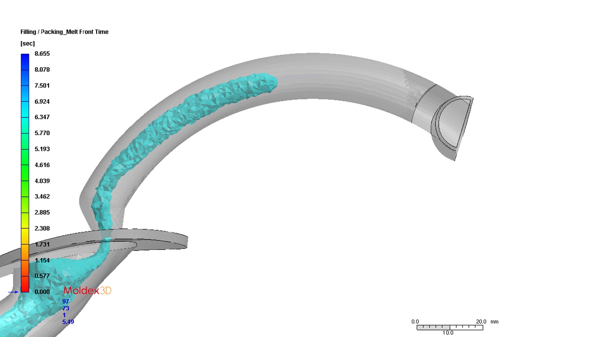
Fig. 6 The core-out result validation between (a) Experiment and (b) Simulation of the water penetration inside the pedal part
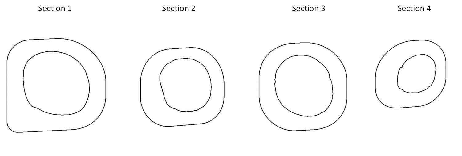
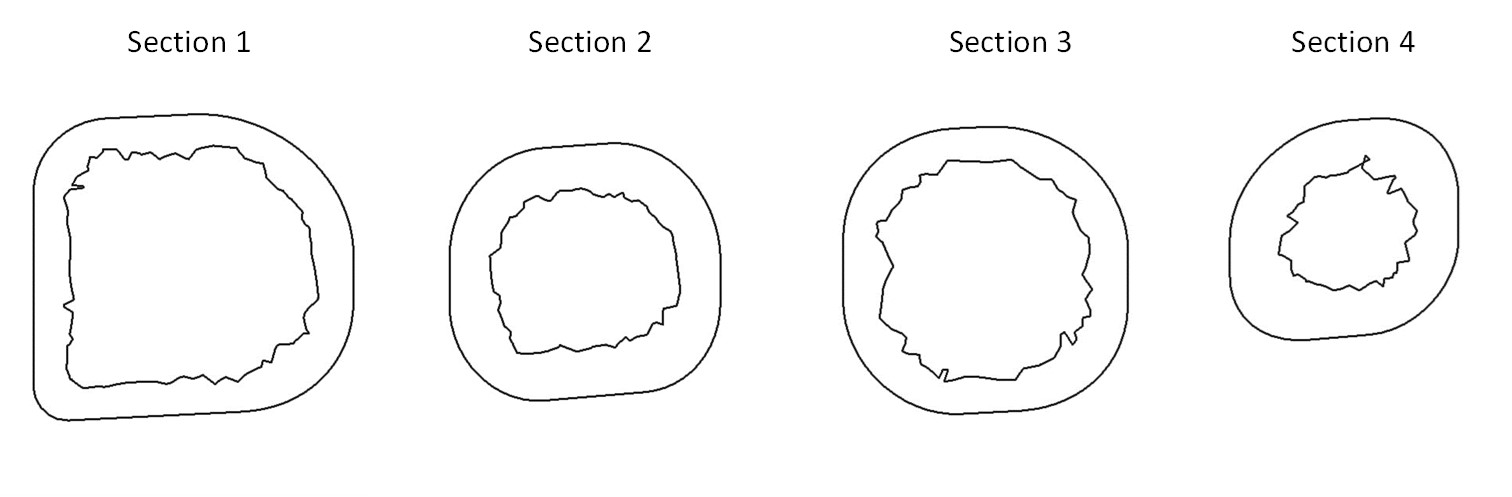
To further examine the core-out performance, Fig. 7 shows the core-out result in 4 different cross-sections (a). Both the experimental (b) and numerical (c) results show that the core-out ratio is higher in areas with a large cross section. On the other hand, Section 4 is closer to the melt entrance and there will be a thicker freezing layer, lower water pressure and smaller back-flow (Fig. 4) as water reaching near the filling end, resulting in less core-out area.
Fig. 8 shows that the experimental and simulation results of the core-out ratio are highly correlated. However, there shows more discrepancy between simulation results than the experiment in the core-out area in Sections 1 and 3 as shown. The cause can be the current laminar flow assumption of the assisted water cannot capture the viscosity induced vortex behavior in the thicker part.
 |
 |
 |
| (a) | (b) | (c) |
Fig. 7 The comparison of the core-out area at (a) 4 different Cross Sections, (b) Experimental Results, and (c) Simulation Results
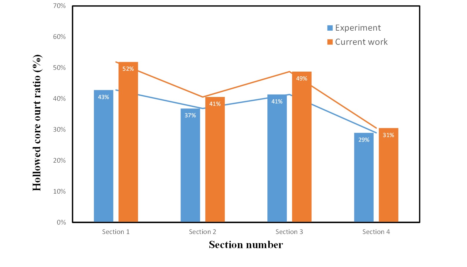
Fig. 8 Comparison of Core-out Ratio between Experimental and Simulation Result
As the water-assisted injection molding technology advances, the full-shot method is gaining importance in recent studies. This article is the first ever research study on the numerical analysis of the full-shot method for the push-back process. A fully three-dimensional molding analysis is performed on the filling process with complex geometry, considering the effect of process conditions on the core-out behavior. The simulation is also validated with the experimental result. This study will serve as a valuable reference for future studies of full-shot methods.
[i] M. L. Wang, R. Y. Chang, C. H. Hsu, Molding Simulation: Theory and Practice, Hanser Publications, 2018
[ii] Yen-Shou Chen, “A Study of the Liquid-Assisted Injection Molding of Thermoplastic Materials” Thesis of Chang Gung University, 2002
[iii] L. Li, Y. Peng and W. Wei, “Recent advances on fluid assisted injection molding technique”, Recent Patents on Mechanical Engineering, Vol.7, No.1, 82-91, 2014
 |
Dr. Jim Hsu
|