
By Jay Vang
With the acceleration of 3D printing technology, the realization of complex (non-conventional) cooling designs is quickly gaining ground in the injection molding industry. Additive manufacturing such as direct metal laser sintering (DMLS) can ALMOST print any imaginable complex cooling circuit design (within the printer platform and print angle limitations) to help control part quality and cycle time.
In today’s economy, time is money. In the injection molding industry, the cooling phase typically determines the length of the overall cycle time. This may be due to factors such as (but not limited to) controlled cooling rate requirements or simply due to the part(s) not reaching safe ejection temperature. Sincecomplex channels can be created near the part surface and hard to reach areas, potential reduction in cooling time and improvement in part quality can be achieved.
Using additive manufacturing for conformal cooling, not only can the designs be complex and contour along the part surface, but it can also potentially be built quicker than conventional machining. This is even more true for multi-cavity molds utilizing additive manufacturing to build conformal cooling channels.
In conjunction with knowing how conformal cooling can help potentially reduce mold build time, reduce cycle time, and increase part quality, utilizing plastic simulation software can help put a relative value in determining the reduction of cycle time and in the improvements of part quality such as distortion. In Fig. 1, direct temperature comparison in the tool can be analyzed to determine cooling efficiency and uniformity between a conventional and a conformal spiral cooling channel. Due to conventional cooling design constraints, heat is not removed from the insert and part as efficiently and as uniformly as the conformal cooling design.
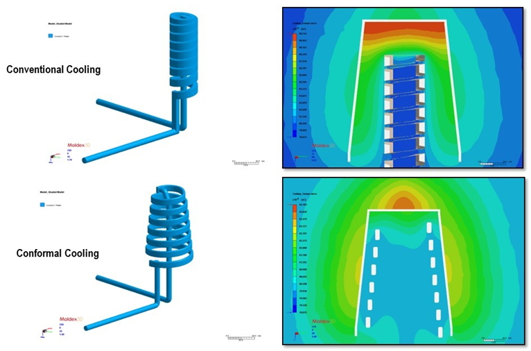
Fig. 1 Simulation results of temperature profile of a conventional cooling and a conformal cooling designs of an insert.
One factor in minimizing warp is to minimize differential shrink. With better mold temperature uniformity, differential shrinkage can be reduced which again helps minimize warp. Fig. 2 compares simulation results at sensor nodes placed on the part surface to determine the temperature profile through an injection molding cycle comparing the two cooling channels above.
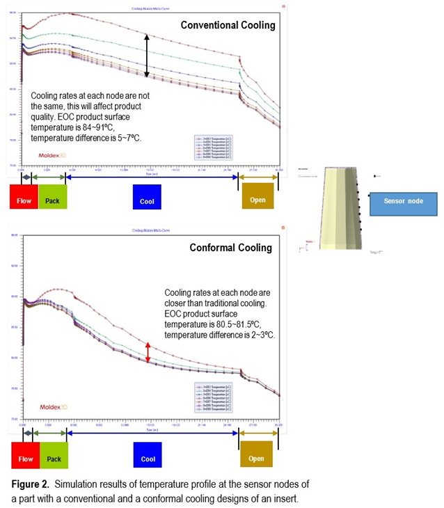
Fig. Simulation results of temperature profile at the sensor nodes of a part with a conventional and a conformal cooling designs of an insert.
The temperature profile indicates a max ∆T of approx. 2~3°C for the case with the conformal cooling design compared to a max ∆T of approx. 5~7°C for the conventional cooling design. Because the differential temperature of the part is reduced, the rate that the material of the part freezes and shrinks are closer and in turn, should yield a part with less warpage.
In summary, the utilization of today’s technology such as vacuum brazing or additive manufacturing to create complex water design to help reduce cycle time and increase part quality is rapidly growing. Coupling conformal cooling design with simulation software can help to prove the validity of conformal cooling in injection molding and help determine potential ROI.
 |
Jay Vang
|