
Multi-cavity system is widely applied in manufacturing small and medium sized products. It is common in both cold and hot runner systems, and includes both low number of cavitation (2 – 8 cavities in a cold runner system) to high number of cavitation (16 – 128 cavities in a hot runner system). Finishing the flow analysis of such a multi-cavity system usually requires long CPU time especially when the cavity number is high since the element count of the whole model can be significantly higher than a single-cavity model.
Moldex3D supports users to prepare the model with symmetry configuration. This feature offers users several layout options for their ½ and ¼ symmetry systems, therefore, users can freely choose the configuration that fits their systems. By utilizing this feature, users can reduce the element count and enhance computation efficiency.
Prepare the symmetry model in Moldex3D Designer
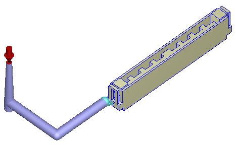
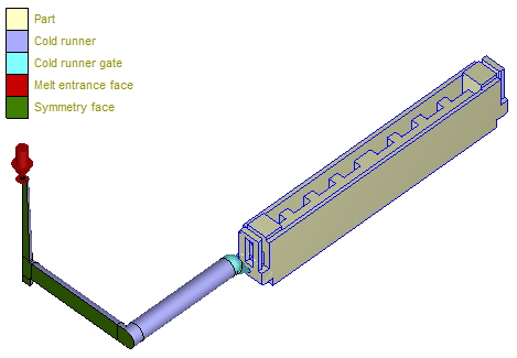
Step 1 Users must set the melt entrance point on a runner curve so that the software can identify the feasibility of creating a symmetry configuration.
Note:
- The runner curve must satisfy the configuration that is feasible for the symmetry configuration.
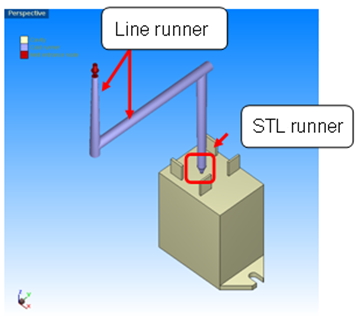
- For the STL runner, please note:
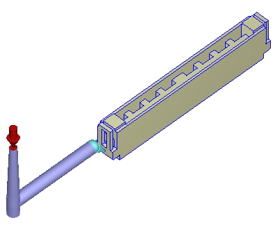
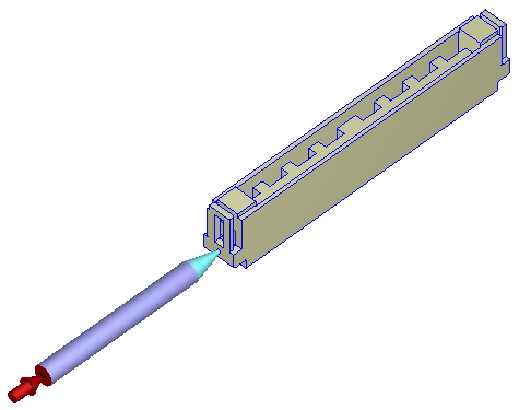
- The runner connected to the part can be in STL format.
- A sprue runner and its next sub-runner must be in line format.
- Users can add sub-runners and the runners connected to the part at any amount either in STL format or line format.
- When connecting line runner with STL runner, make sure to attach the line to the wall of STL runner.
| Feasible | Not Feasible | STL Runner | ||
 |
 |
 |
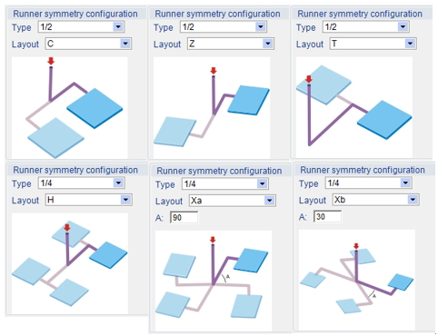
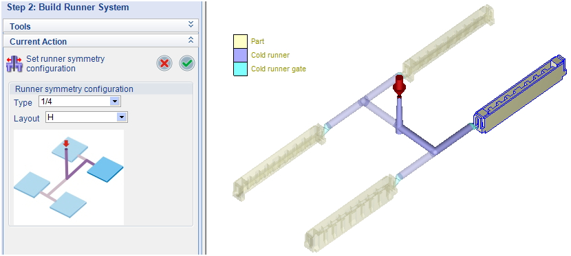
Step 2 Click Set Symmetry Configuration option: Set Runner System to launch the setting panel, and the workspace will also demonstrate the result in real time.
Step 3 Specify the symmetry Type, Layout, and/or Parameter (A)
Note:
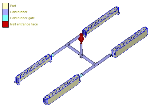
1. The window will demonstrate the full model.
2. The Parameter (A) only exists in ¼-type configuration with X runner layout.
3. Some layouts will be available only when the runner curve configuration in Step 1 satisfies the feasibility of those layouts.
Step 4 Click OK to confirm the setting or Cancel to withdraw. Then, complete model preparation, analysis settings, and run Moldex3D simulation with regular workflow.
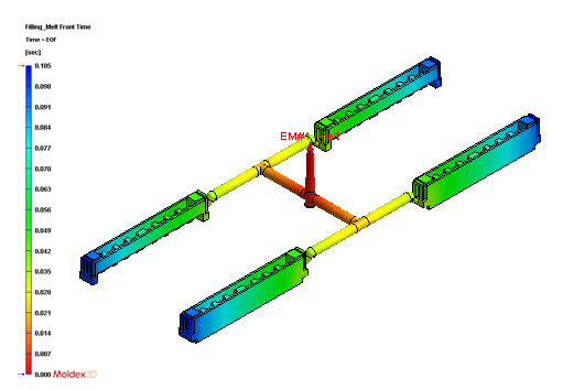
Comparison (Benefit of using symmetry setting)
| Full Model | Symmetry Model | |
 |
 |
|
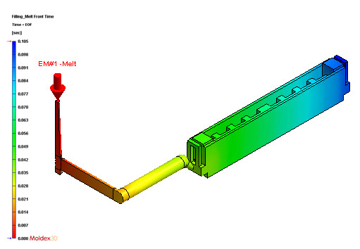
| The model is purposely made as the full model (the two cavities are made here). | The quarter-cut runner will appear in the display right after the runner solid mesh is generated. | |
| Element count: Part 433,344 Runner 315,548 Runner-part 748,892 |
Element count: Part 108,336 Runner 109,692 Runner-part 218,028 |
|
| 3.43 times higher element count | Reference | |
 |
 |
|
| Flow analysis CPU time: 36 min | Flow analysis CPU time: 12 min | |
| 3 times longer CPU time | Reference |